
A rudder angle feedback device

A technology of feedback device and rudder angle, which is applied in the direction of rudder steering, etc., can solve the problems of reduced detection accuracy of rudder angle feedback device, inability to meet the high-precision requirements of dynamic positioning, and inability to accurately reflect the rudder angle of azimuth propellers, etc. To achieve the effect of improving the detection accuracy

Active Publication Date: 2016-03-09
WUHAN MARINE MACHINERY PLANT
View PDF5 Cites 0 Cited by
  • Summary
  • Abstract
  • Description
  • Claims
  • Application Information

AI Technical Summary

Problems solved by technology

[0005] In the existing rudder angle feedback device, when the slewing bearing rotates forward or reverse, one side of the teeth of the pinion is in contact with the teeth of the outer ring gear, and the other side of the teeth of the pinion is in contact with the teeth of the outer ring gear. There is a certain gap between them. When the slewing bearing changes direction, the slewing bearing needs to rotate a certain angle first, so that the teeth of the outer ring gear can contact the other side of the pinion teeth, and then drive the pinion to move together. Since the pinion cannot move in time with the slewing bearing after reversing, the pinion cannot accurately reflect the rudder angle of the azimuth propeller, which will directly lead to a decrease in the detection accuracy of the rudder angle feedback device, which cannot meet the high requirements of dynamic positioning. Accuracy requirements

Method used


Image

  • A rudder angle feedback device
  • A rudder angle feedback device
  • A rudder angle feedback device

Examples


Embodiment

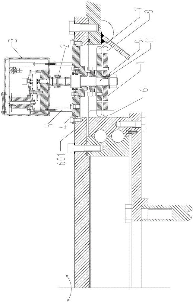
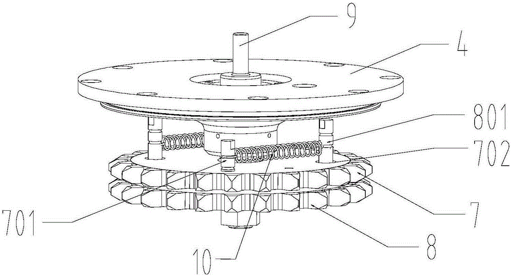
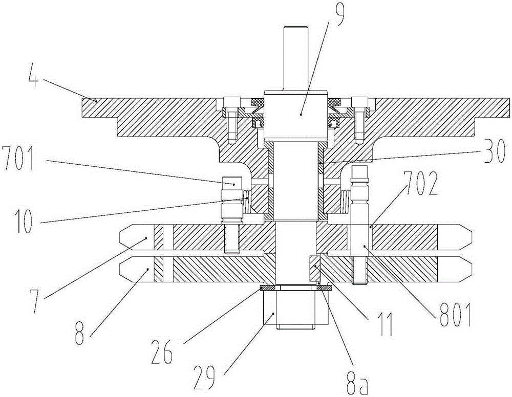
[0033] An embodiment of the present invention provides a rudder angle feedback device, such as figure 1 As shown, the rudder angle feedback device includes a rudder angle feedback transmission assembly 1, a coupling 2 and a rudder angle feedback sensor assembly 3, combined with figure 2 and image 3 The rudder angle feedback transmission assembly 1 includes: a bracket 4 for fixed connection with the suspension bracket 601 of the slewing support, a gear shaft 9, and a first gear 7 and a second gear 8 respectively meshing with the outer ring gear 6 of the slewing support , the gear shaft 9 is rotatably installed on the bracket 4, the first gear 7 and the second gear 8 are coaxially installed on one end of the gear shaft 9, the first gear 7 and the gear shaft 9 are in clearance connection, the second gear 8 and the gear shaft 9 is fixedly connected, and the other end of the gear shaft 9 is connected through the transmission shaft coupling 2 and the transmission shaft of the rud...


PUM


Abstract

The invention discloses a rudder angle feedback device and belongs to the field of ship thruster devices. The rudder angle feedback device comprises a rudder angle feedback transmission assembly. The rudder angle feedback transmission assembly comprises a support fixedly connected with a pivoting support, a gear shaft, a first gear and a second gear, wherein the first gear and the second gear are respectively meshed with an outer ring gear of the pivoting support. The first gear is provided with a first rod and a through hole, the second gear is provided with a second rod corresponding to the through hole, the hole diameter of the through hole is larger than the diameter of the second rod, the second rod penetrates through the through hole and is connected with the first rod through an elastic component which is in a stretched state, so that the first gear and the second gear abut against the gear faces of two adjacent teeth of the outer ring gear of the pivoting support respectively. The two small gears are meshed with the tooth faces of the two adjacent teeth of the outer ring gear of the pivoting support respectively, so that gaps for reversing transmission of the gears and the outer ring gear of the pivoting support are eliminated, wherein the gears are meshed with the outer ring gear of the pivoting support.

Description

technical field [0001] The invention relates to the field of ship thruster devices, in particular to a rudder angle feedback device. Background technique [0002] The azimuth propeller on a ship is a new type of ship propeller. In addition to generating thrust like a common propeller, it can also change the thrust direction within a 360° range, thereby helping the ship to achieve a 360° turn. Azimuth thrusters are usually applied to ships or drilling platforms that require dynamic positioning. The dynamic positioning system of a ship or drilling platform usually includes a position measurement system and a dynamic positioning control system. The required thrust and the azimuth of the thrust, and the dynamic positioning system controls the azimuth propeller to adjust the rudder angle according to the thrust and the azimuth of the thrust to issue the thrust. [0003] The azimuth thruster usually needs to be used together with the rudder angle feedback device. The rudder angle...

Claims


Application Information

Patent Timeline
Patent Type & Authority Patents(China)
IPC IPC(8): B63H25/36
Inventor 邱晓峰王建强邹斌李磊郭俊雷华堂邹波
Owner WUHAN MARINE MACHINERY PLANT
Learn More