Chain cleaning machine

A chain cleaning and washing machine technology, applied to conveyors, cleaning methods and appliances, chemical instruments and methods, etc., can solve problems such as low work efficiency, waste of energy, etc., achieve easy maintenance, convenient operation, and improve work efficiency Effect

Inactive Publication Date: 2014-03-26
DALIAN SHENGLONG MACHINERY
View PDF0 Cites 2 Cited by
  • Summary
  • Abstract
  • Description
  • Claims
  • Application Information

AI Technical Summary

Problems solved by technology

At the same time, because the return trip does not work, the work efficiency is low and energy consumption is wasted

Method used


Image

  • Chain cleaning machine
  • Chain cleaning machine
  • Chain cleaning machine

Examples


Embodiment Construction

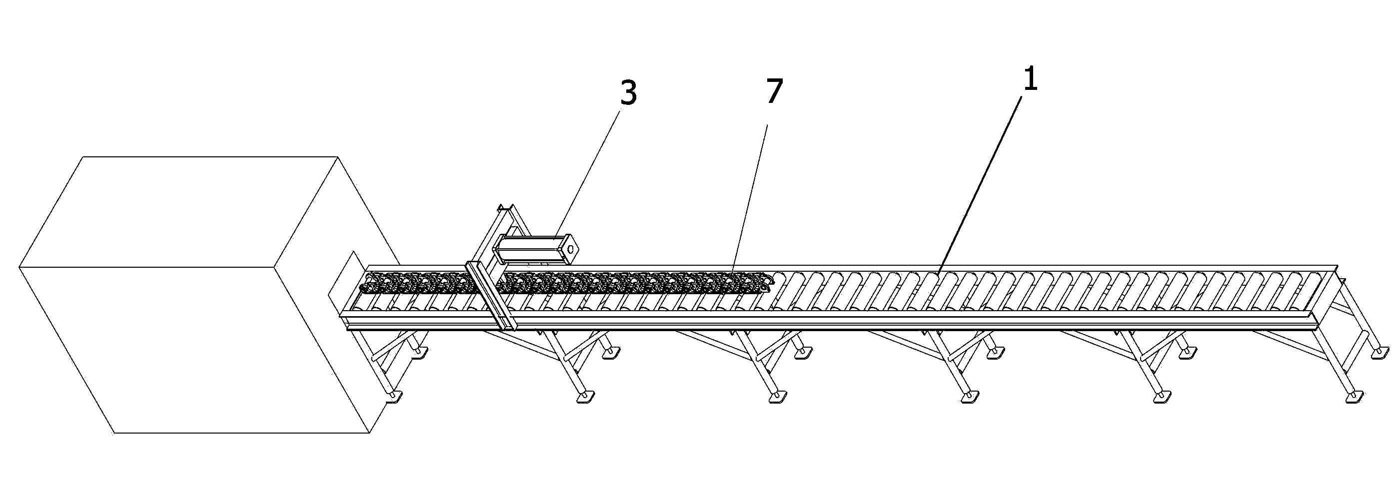
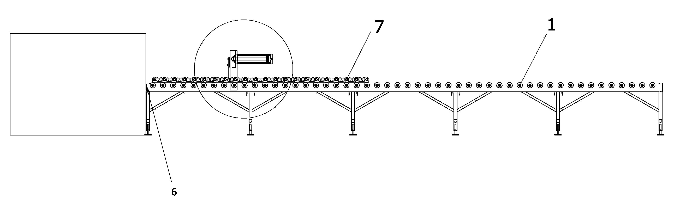
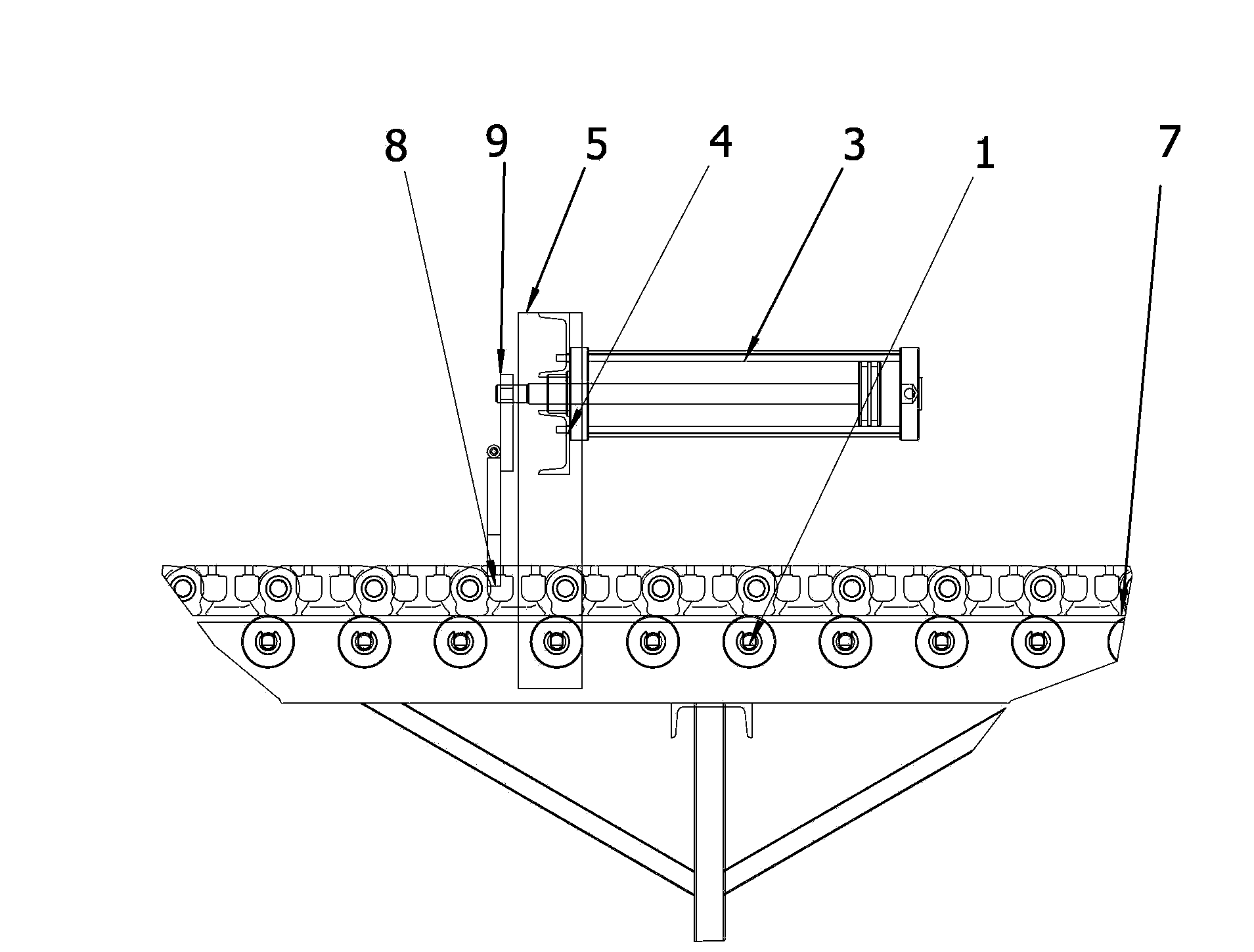
[0024] Such as Figure 5-9 As shown, the chain cleaning machine of the present invention includes a material guide frame 1 formed by side-by-side rollers, and a cleaning machine 6 provided at one end of the material guide frame 1 . The improvement of the present invention lies in that the material guide frame 1 is provided with a "door" frame body composed of vertical beams 5 and cross beams 4, the "door" frame bodies are two opposite sides, and the two "door" frame bodies The body is provided with a cooperating gear 21 and rack 22 through the supporting beam, and the two ends of the rack 22 are respectively hinged to the push plates 8 through a seat plate 9, and each push plate 8 faces away from the direction of the cleaning machine 6 respectively to rotate around the hinge axis. 10 one-way rotation mode settings. In addition, the rack 22 is also connected to an actuator that drives the rack to reciprocate.

[0025] In a preferred mode, the actuator is selected from the cyl...


PUM


Abstract

The invention discloses a chain cleaning machine. The chain cleaning machine comprises a material guiding frame (1) and a cleaning machine body (6), wherein the material guiding frame (1) is formed by rollers side by side, and the cleaning machine body (6) is arranged at one end of the material guiding frame (1). The material guiding frame is provided with n-shaped frames composed of vertical beams (5) and transverse beams (4), and the two n-shaped frames are oppositely arranged on the two sides of the material guiding frame. A gear (21) and a rack (22) are matched with each other and arranged between the two n-shaped frames through a supporting beam, the two ends of the rack (22) are hinged to push plates (8) through base plates (9) respectively, and each push plate (8) rotates around a hinge joint shaft in the direction opposite to the cleaning machine body (6). In addition, the rack (22) is further connected with an executing mechanism which drives the rack to reciprocate. The push plates and stirring forks are arranged in the two directions, and therefore a conveying mechanism of the cleaning machine can move in two directions when the executing mechanism reciprocates, and therefore work efficiency is multiplied, and efficiency of the executing mechanism is greatly brought into full play.

Description

technical field [0001] The present invention relates to a mechanism for cleaning chains, and more particularly, to an improvement in the transmission mechanism of a chain washer. Background technique [0002] During the press-fitting process of the chain-rail joint assembly, since part of the lubricating oil remains on the chain surface, the oil must be removed before the anti-corrosion treatment, otherwise it will affect the adhesion of the paint film, thereby affecting the product quality. After cleaning the chain-rail joint assembly When it is completed, because the chain rail joint assembly is heavy, and the chain rail joint assembly must pass through a cleaning machine with high-temperature cleaning fluid, it is difficult for ordinary transmission mechanisms to bear. [0003] Cleaning methods in the prior art such as Figure 1-4 As shown, the cylinder push-pull intermittent motion mechanism is adopted. The chain assembly 7 is placed on the material guide frame 1 formed...

Claims


Application Information

Patent Timeline
Patent Type & Authority Applications(China)
IPC IPC(8): B65G25/08B08B13/00
Inventor 杨兴道
Owner DALIAN SHENGLONG MACHINERY
Why Eureka
Try Eureka