Winch brake

A technology of winches and torsion springs, which is applied in the direction of hoisting devices, etc., can solve the problems of easy damage, failure, and short service life, and achieve the effects of simple structural assembly, reducing accidents, and prolonging service life

Active Publication Date: 2014-03-26
NINGBO LIANDA WINCH
View PDF6 Cites 1 Cited by
  • Summary
  • Abstract
  • Description
  • Claims
  • Application Information

AI Technical Summary

Problems solved by technology

[0003] In order to overcome the above-mentioned shortcomings, the purpose of the present invention is to provide a winch brake in the field, so that it can solve the technical problems that existing similar products are easy to damage and fail, and have a short service life.

Method used


Image

  • Winch brake
  • Winch brake

Examples


Embodiment Construction

[0016] Now in conjunction with accompanying drawing, the present invention will be further described.

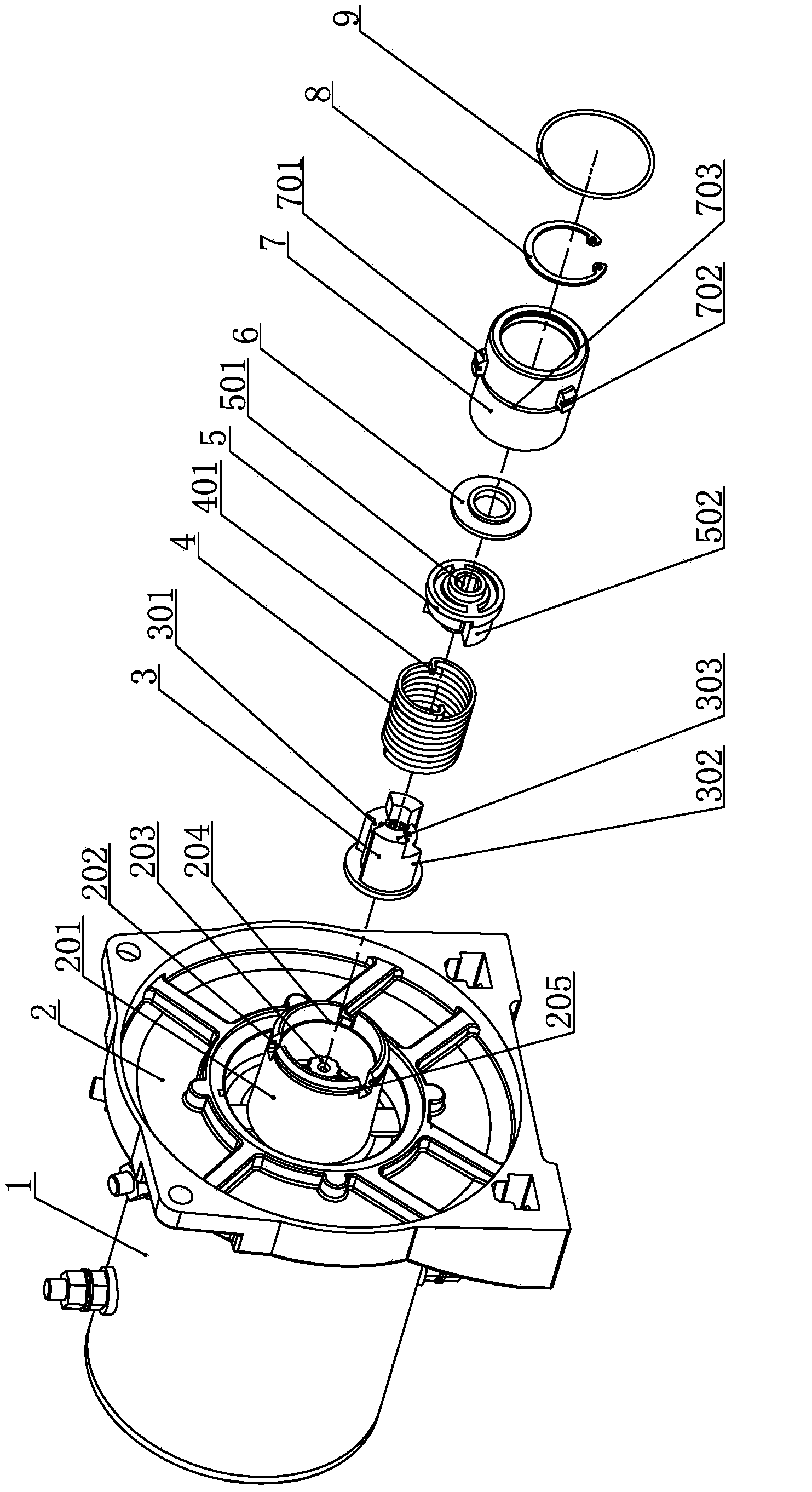
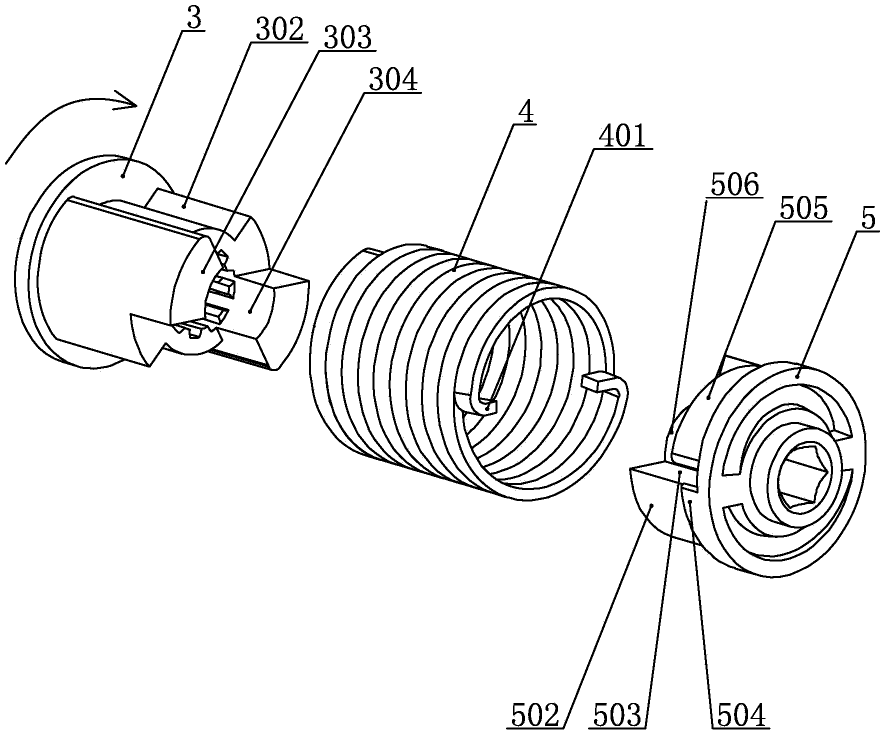
[0017] Such as figure 1 , figure 2 As shown, the winch brake includes a driving seat 3, an anti-expansion torsion spring 4, a passive seat 5, a positioning bush 6, and a brake sleeve 7. The driving seat is connected to the output end of the motor 1, and the motor is connected to the motor bracket 2. The motor bracket is provided with The sleeve seat 201 where the brake sleeve is socketed, the active seat, the reverse expansion torsion spring, the passive seat, and the positioning bush are connected in sequence, and are limited in the brake sleeve by the circlip 8, wherein the reverse expansion torsion spring is in contact with the brake sleeve in the initial state The frictional contact between the inner walls is smaller than the frictional force between the reverse expansion torsion spring and the brake sleeve during braking. The specific structure and connection are as ...


PUM


Abstract

The invention relates to a winch brake which comprises a drive seat, an inverse expansion torsion spring, a driven seat, and a brake sleeve. The drive seat and the driven seat are coaxially connected and rotate relative to each other. The inverse expansion torsion spring is connected to a column section of the drive seat and a column section of the driven seat in a sleeved mode. The drive seat, the inverse expansion torsion spring and the driven seat constitute a whole body and are arranged in the brake sleeve. An outer ring of the inverse expansion torsion spring is in friction contact with the inner wall of the brake sleeve in an initial state, and the initial friction force is smaller than the friction force formed by the inverse expansion torsion spring and the inner wall of the brake sleeve at braking time. A flange blocking a corresponding bending foot bending part is arranged on the circumferential face of the column section of the driven seat and on one side where a bending foot groove pushes a corresponding bending foot to enable the inverse expansion torsion spring to expand. The size of the outer diameter formed by the flange relative to the axis of the driven seat is not smaller than the radius of the outer ring of the inverse expansion torsion spring. Through the flange, the inverse expansion torsion spring can still be driven to realize brake when the bending foot of the torsion spring is damaged, so that the stability and the reliability of the winch brake are improved, and traction is prevented from failing. The winch brake is suitable for various winch brake devices or structural improvement of like products.

Description

technical field [0001] The invention relates to a winch, in particular to a winch brake. Background technique [0002] A winch is an auxiliary device used for vehicle self-rescue or as a traction device. Because the traditional winch has no brake device, the problem of traction failure often occurs. For this reason, the existing winch is designed with an automatic braking function, that is, when the winch stops, the traction rope of the winch can be automatically locked to prevent traction failure. For example, the authorized announcement number CN202369311U published in the Chinese patent literature, the authorized announcement date is August 8, 2012, and the name of the utility model is "backstop", which includes the first coupling, the second coupling, the coupling sleeve, and the brake pad. Plates, torsion springs, retaining rings, steel sleeves, and dust-proof bearings drive the torsion springs to expand outward through coupling two, and the torsion springs rub against...

Claims


Application Information

Patent Timeline
Patent Type & Authority Applications(China)
IPC IPC(8): B66D5/32
Inventor 崔晓君
Owner NINGBO LIANDA WINCH
Why Eureka
Try Eureka