Ultraviolet reactor
A reactor and ultraviolet technology, applied in the field of ultraviolet reactors, can solve the problems of reduced efficiency, large lamp distance deviation, and high fluid flow rate, and achieve the effect of improving efficiency
- Summary
- Abstract
- Description
- Claims
- Application Information
AI Technical Summary
Problems solved by technology
Method used
Image
Examples
Embodiment 1
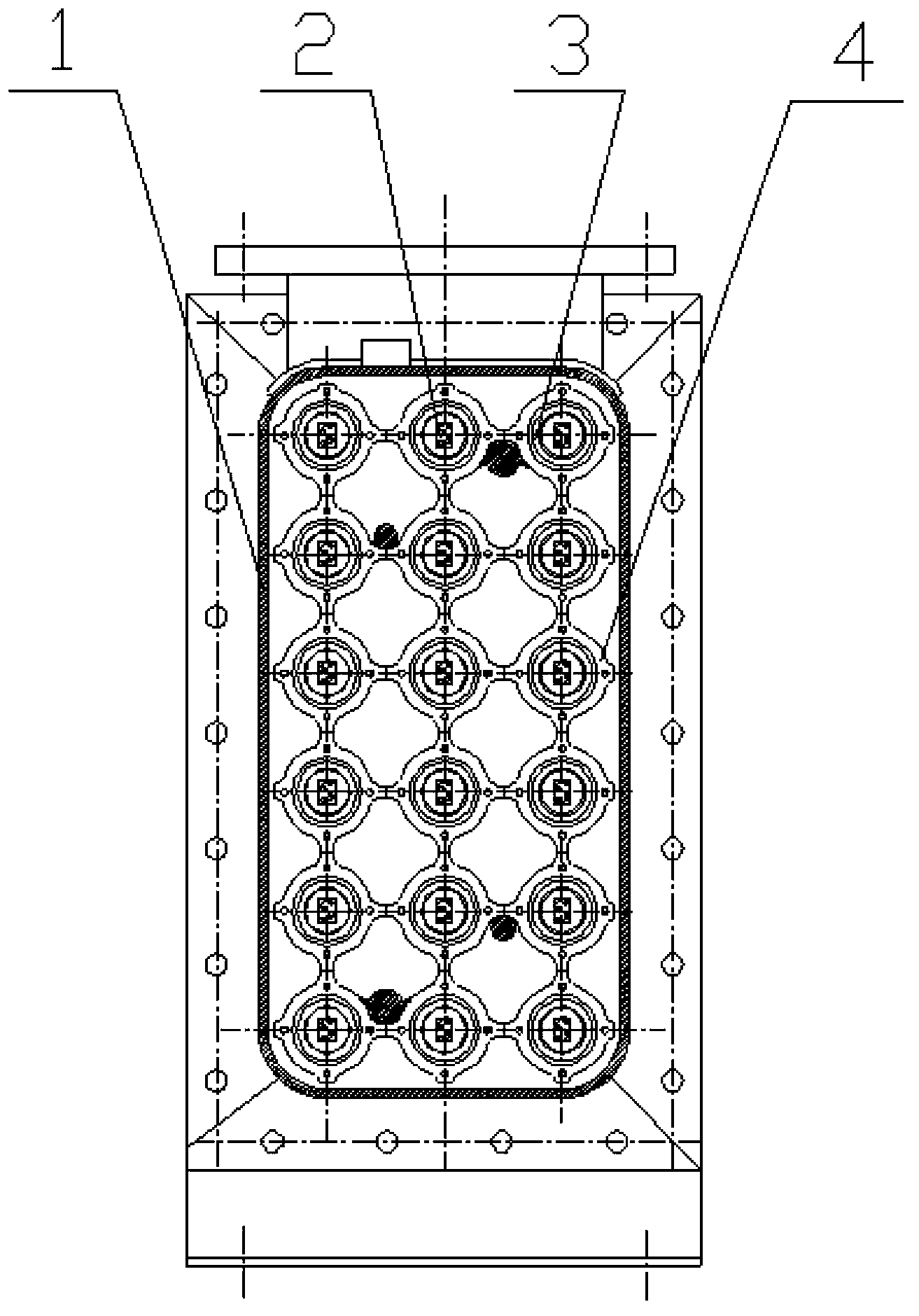
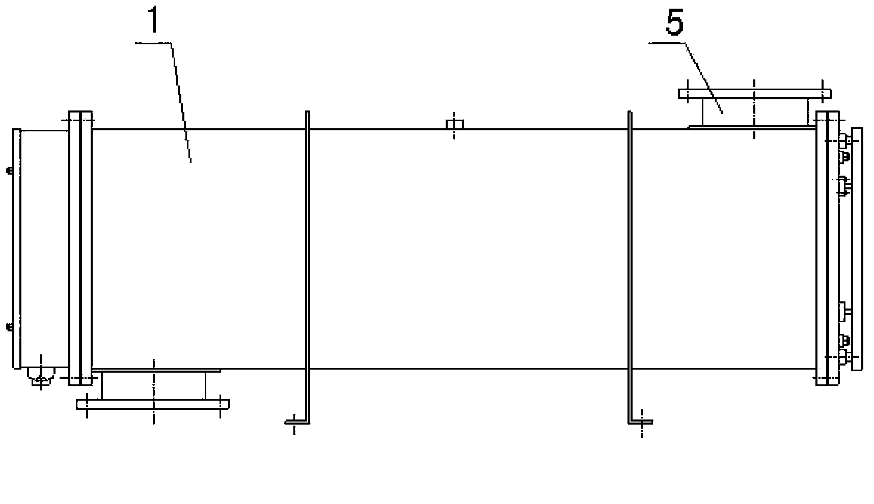
[0014] The ultraviolet reactor described in this embodiment mainly includes a shell (1), an ultraviolet lamp (2), a quartz protective sleeve (3), a cleaning device (4), and a water inlet and outlet pipe (5), wherein the ultraviolet lamp ( 2) Placed in the quartz protective sleeve (3) and arranged in the housing (1) in a matrix form, the cleaning device (4) is placed in the housing (1) and used together with the quartz protective sleeve (3) , the water inlet and outlet pipes (5) are respectively placed on both sides outside the housing (1).
[0015] In the ultraviolet reactor described in this embodiment, the distance between any two adjacent quartz protective sleeves (3) is 45 mm, and the quartz protective sleeves (3) arranged in a matrix are connected to the housing ( 1) The distance of the inner wall is 23mm.
[0016] In the ultraviolet reactor described in this embodiment, the cross-section of the housing (1) is rectangular, and the four corners of the housing (1) are circ...
Embodiment 2
[0021] The ultraviolet reactor described in this embodiment mainly includes a shell (1), an ultraviolet lamp (2), a quartz protective sleeve (3), a cleaning device (4), and a water inlet and outlet pipe (5), wherein the ultraviolet lamp ( 2) Placed in the quartz protective sleeve (3) and arranged in the housing (1) in a matrix form, the cleaning device (4) is placed in the housing (1) and used together with the quartz protective sleeve (3) , the water inlet and outlet pipes (5) are respectively placed on both sides outside the housing (1).
[0022] In the ultraviolet reactor described in this embodiment, the distance between any two adjacent quartz protective sleeves (3) is 40mm, and the quartz protective sleeves (3) arranged in a matrix are connected to the housing ( 1) The distance of the inner wall is 25mm.
[0023] In the ultraviolet reactor described in this embodiment, the cross-section of the housing (1) is rectangular, and the four corners of the housing (1) are circu...
Embodiment 3
[0028] The ultraviolet reactor described in this embodiment mainly includes a shell (1), an ultraviolet lamp (2), a quartz protective sleeve (3), a cleaning device (4), and a water inlet and outlet pipe (5), wherein the ultraviolet lamp ( 2) Placed in the quartz protective sleeve (3) and arranged in the housing (1) in a matrix form, the cleaning device (4) is placed in the housing (1) and used together with the quartz protective sleeve (3) , the water inlet and outlet pipes (5) are respectively placed on both sides outside the housing (1).
[0029] In the ultraviolet reactor described in this embodiment, the distance between any two adjacent quartz protective sleeves (3) is 50 mm, and the quartz protective sleeves (3) arranged in a matrix are connected to the housing ( 1) The distance of the inner wall is 20mm.
[0030] In the ultraviolet reactor described in this embodiment, the cross-section of the housing (1) is rectangular, and the four corners of the housing (1) are circ...
PUM
 Abstract
Description
Claims
Application Information
 - R&D
- Intellectual Property
- Life Sciences
- Materials
- Tech Scout
- Unparalleled Data Quality
- Higher Quality Content
- 60% Fewer Hallucinations
Browse by: Latest US Patents, China's latest patents, Technical Efficacy Thesaurus, Application Domain, Technology Topic, Popular Technical Reports.
© 2025 PatSnap. All rights reserved.Legal|Privacy policy|Modern Slavery Act Transparency Statement|Sitemap|About US| Contact US: help@patsnap.com


