Hydraulic rock drilling machine

A rock drilling rig and rock drilling rig technology, applied in drilling equipment, earthwork drilling, drilling equipment and methods, etc., can solve the problems of high price, poor slag discharge capacity of air compressor, low power density, etc., and save installation time. and cost, quick and convenient disassembly, and the effect of improving slag discharge capacity

Active Publication Date: 2014-03-26
贵阳矿山机器厂有限公司
View PDF8 Cites 4 Cited by
  • Summary
  • Abstract
  • Description
  • Claims
  • Application Information

AI Technical Summary

Problems solved by technology

[0002] At present, the high difficulty and particularity of road construction and related projects in our country have strengthened our dependence on high-performance rock drilling rigs. Our country spends a lot of money every year to import a considerable number of rock drilling rigs from abroad. funds, and the maintenance and repair of the trolley is quite difficult
The integrated hydraulic rock drilling machine has the advantages of high power density and high operating efficiency, but the technical requirements are relatively high and the price is expensive. The price of each unit is more than 2 million yuan
Pneumatic rock drilling machinery has the advantages of simple structure and low technical requirements, but the power density is low, the operating efficiency is low, and the entire system is large in size, and usually needs to be used with an air compressor, which is costly
[0003] When the existing excavator hydraulic rock drilling air compressor device is installed on the excavator platform, the back pressure caused by too long pipeline is too high, the slag discharge ability of the air compressor is poor, the pipeline layout is complicated, and it is inconvenient to install

Method used


Image

  • Hydraulic rock drilling machine
  • Hydraulic rock drilling machine
  • Hydraulic rock drilling machine

Examples


Embodiment Construction

[0017] The present invention will be further described below in conjunction with the accompanying drawings and specific embodiments, but the scope of protection is not limited to the description.

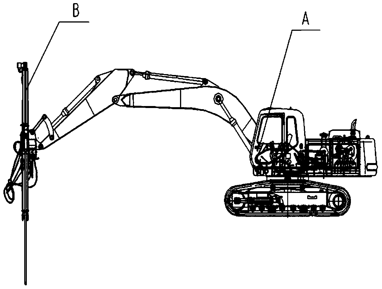
[0018] Such as Figure 1-3 As shown, the present invention is a hydraulic rock drilling rig, which is composed of a hydraulic carrier machine A and a drilling rig B. The hydraulic carrier machine A is an excavator, a loader or a forklift. The working device is machine base, using the hydraulic oil provided by the hydraulic system of the hydraulic carrier machine and the optional air compressor device 4 as the power source, and the drilling rig B is installed at the front end of the working section of the hydraulic carrier machine A. Taking an excavator as an example, the drilling rig B is installed at the bucket position of the excavator.

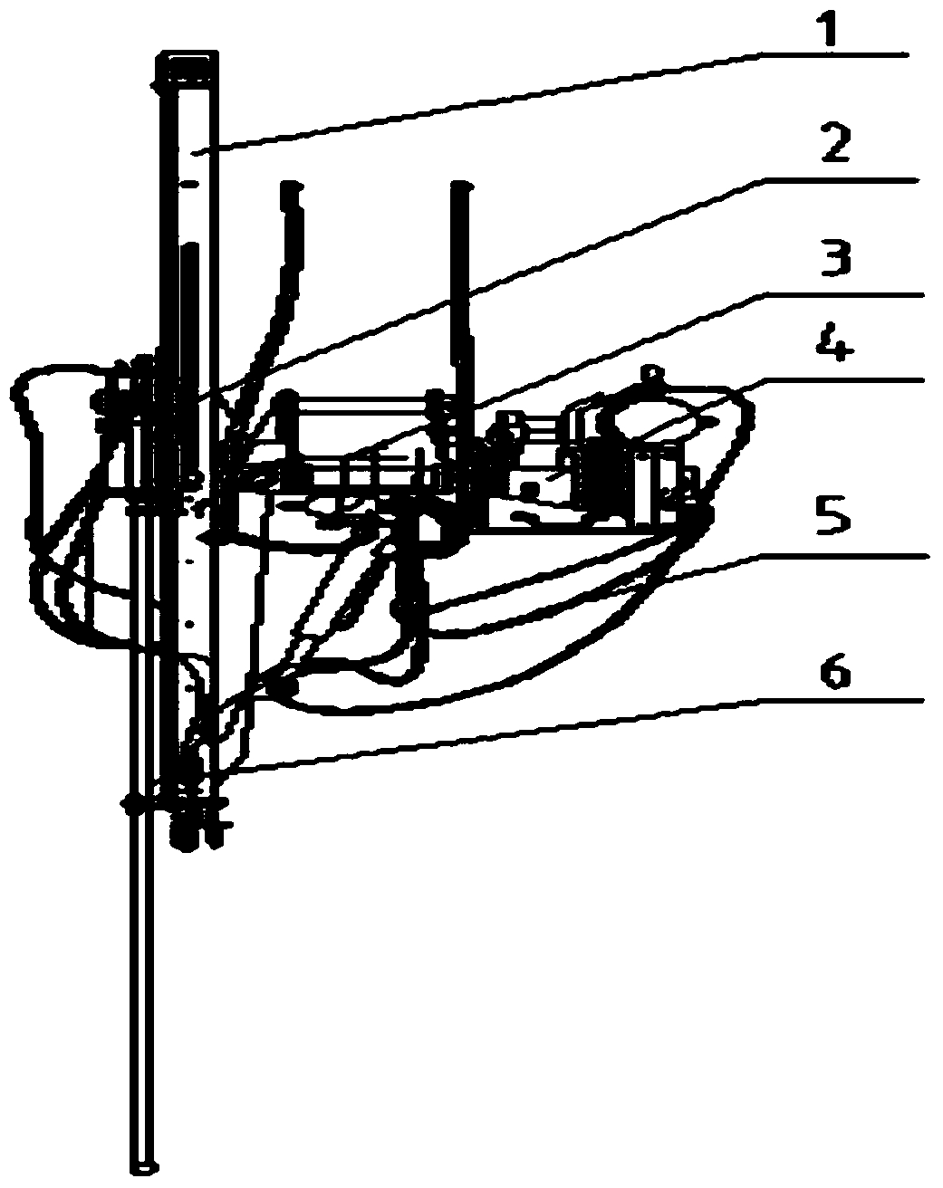
[0019] The drilling rig B is composed of a propulsion beam 1, a rock drill head 2, a swing mechanism 3, an air compressor device 4, a hydraulic...


PUM


Abstract

The invention relates to engineering machines, in particular to a hydraulic rock drilling machine. The hydraulic rock drilling machine is composed of a hydraulic carrier machine A and a drilling machine B. The hydraulic carrier machine A is an excavator, or a loader or a forklift, and according to the hydraulic rock drilling machine, a working device at the front end of the hydraulic carrier machine A serves as a machine base. Hydraulic oil provided by a hydraulic system of the hydraulic carrier machine and a selectively matched air compressor are used as power sources, and the drilling machine B is installed at the front end of the working section of the hydraulic carrier machine A. The working device at the front end of the excavator, or the loader or the forklift is adopted as the machine base in cooperation with the drilling machine to perform rapid and efficient rock drilling. The hydraulic rock drilling machine is rapid and convenient to install and detach, easy to maintain, low in cost and high in efficiency.

Description

technical field [0001] The invention relates to an engineering machine, in particular to a hydraulic rock drilling rig. Background technique [0002] At present, the high difficulty and particularity of road construction and related projects in our country have strengthened our dependence on high-performance rock drilling rigs. Our country spends a lot of money every year to import a considerable number of rock drilling rigs from abroad. Funds, and the maintenance and repair of trolleys are also quite difficult. The integrated hydraulic rock drilling machine has the advantages of high power density and high operating efficiency, but it has relatively high technical requirements and is expensive, and the price of each unit is more than 2 million yuan. Pneumatic rock drilling machinery has the advantages of simple structure and low technical requirements, but the power density is low, the operating efficiency is low, and the entire system is bulky, and it usually needs to be ...

Claims


Application Information

Patent Timeline
Patent Type & Authority Applications(China)
IPC IPC(8): E21B7/02E21B44/00
Inventor 刘斌宋晓林邓良抚涂治国焦林増龙奇林罗平付庆能
Owner 贵阳矿山机器厂有限公司
Why Eureka
Try Eureka