
Technology for engine continuous variable valve timing, phase position and lift

A valve timing and variable technology, which is applied in the direction of engine components, machines/engines, mechanical equipment, etc., can solve the problems that the valve phase and lift cannot be changed, and achieve simple structure, increased intake air volume, and smooth intake and exhaust Effect

Inactive Publication Date: 2014-03-26
贾开继
View PDF6 Cites 2 Cited by
  • Summary
  • Abstract
  • Description
  • Claims
  • Application Information

AI Technical Summary

Problems solved by technology

[0003] In order to overcome the deficiency that most of the existing engines cannot change the valve phase and lift, the present invention provides an engine continuously variable valve timing, phase and lift technology, which can continuously change the timing and phase at different engine speeds. and lift

Method used


Image

  • Technology for engine continuous variable valve timing, phase position and lift
  • Technology for engine continuous variable valve timing, phase position and lift
  • Technology for engine continuous variable valve timing, phase position and lift

Examples


Embodiment Construction

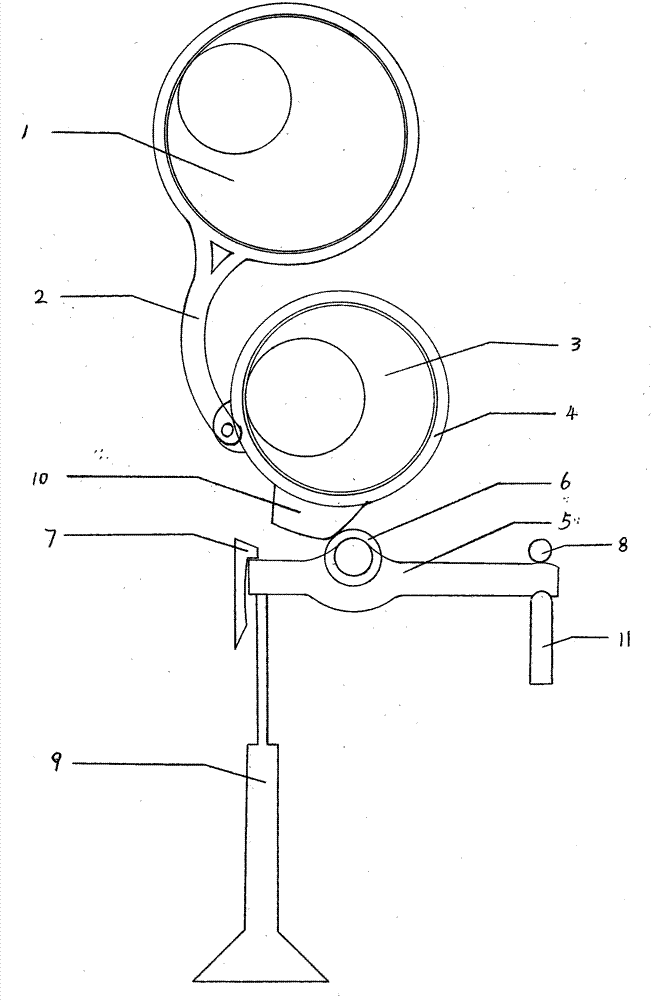
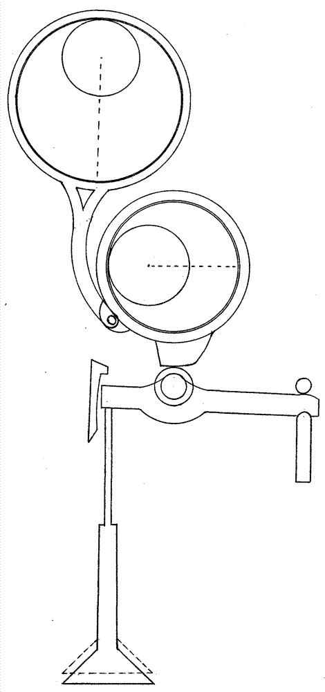
[0017] exist figure 1 Among them, the eccentric camshaft (1) is connected with the connecting rod (2), the shaft sleeve (4) is installed on the eccentric adjustment shaft (3), and the connecting rod (2) is connected with the shaft sleeve (4). The eccentric adjustment shaft (3) is in a static state when it does not need to be adjusted, and when the engine speed rises, it is adjusted according to the speed requirement. The eccentric camshaft (1) is driven by the rod where the small circle is located, driving the eccentric camshaft to rotate, figure 2 The middle eccentric camshaft (1) rotates clockwise to drive the connecting rod (2) to move, and the connecting rod (2) drives the shaft sleeve (4) to move, and the shaft sleeve (4) performs reciprocating motion. exist figure 2 The middle opening convex surface (10) is under the shaft sleeve (4) and reciprocates together with the shaft sleeve. When the opening convex surface (10) moves to the position of the rocker ball (6), it ...


PUM


Abstract

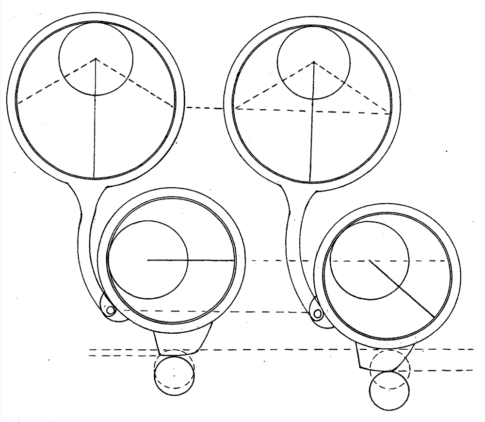
Provided is a technology for engine continuous variable valve timing, phase position and lift. The technology is composed of two eccentric shafts, a connecting rod, a shaft sleeve and a rocker arm below the shaft sleeve. The connecting rod and the shaft sleeve are connected with the two eccentric shafts respectively. The first eccentric shaft is used as a cam shaft, the connecting rod connected with the first eccentric shaft drives the outer sleeve of the second eccentric shaft to do reciprocating motion, an open convex face on the lower portion of the outer sleeve is in contact with a rolling ball on the rocker arm to open an air valve, the second eccentric shaft rotates through a set angle, the shaft sleeve on the outer edge of the second eccentric shaft is made to move vertically, and the more the shaft sleeve moves downwards, the more the air valve is opened by the open convex face through the rolling ball of the rocker arm, and the larger the lift of the air valve is. With the increase of the lift of the air valve, the contact track of the open convex face and the rolling ball is continuously changed, the air valve is made to be opened in advance and closed in a delayed mode continuously so that the aim of increasing the phase position continuously can be achieved, and the air valve timing can be continuously changed due to the fact that the air valve is continuously opened in advance.

Description

Technical field [0001] The invention relates to a technology for continuously changing engine valves, especially a technology that can simultaneously change valve lift, valve timing and valve timing, and is continuously changing. Background technique [0002] Most of the current engines can only change the valve timing technology, a small part can change the lift but only two-stage, only a few high-end models are equipped with this technology, and changing the valve phase and lift technology directly affects the work of the engine efficiency. Today, when air pollution is serious and non-renewable resources are increasingly scarce, it is very important to improve the working efficiency of engines for energy conservation and environmental protection. Contents of the invention [0003] In order to overcome the deficiency that most of the existing engines cannot change the valve phase and lift, the invention provides an engine continuously variable valve timing, phase and lif...

Claims


Application Information

Patent Timeline
IPC IPC(8): F01L1/34F01L13/00
Inventor 贾开继
Owner 贾开继
Learn More