
Mechanism for continuously adjusting engine valve lift

An engine valve and adjustment mechanism technology, which is applied to engine components, machines/engines, mechanical equipment, etc., and can solve the problems of complex structure, large number of variable valve mechanism parts, and difficulty in ensuring reliability.

Active Publication Date: 2014-03-26
GREAT WALL MOTOR CO LTD
View PDF10 Cites 9 Cited by
  • Summary
  • Abstract
  • Description
  • Claims
  • Application Information

AI Technical Summary

Problems solved by technology

The technical solution of this patent can realize the continuous adjustment of the valve lift, and at the same time achieve the purpose of reducing the load of the valve lift adjustment mechanism, but because the first cam and the transmission part are in line contact, there is a problem of large wear between the parts; At the same time, the variable valve mechanism has a large number of parts and a complex structure, which not only increases the difficulty and cost of the manufacturing process of the parts, but also makes it difficult to guarantee the reliability of the mechanism operation.

Method used


Image

  • Mechanism for continuously adjusting engine valve lift
  • Mechanism for continuously adjusting engine valve lift
  • Mechanism for continuously adjusting engine valve lift

Examples


Embodiment Construction

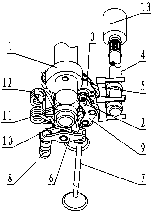
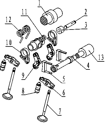
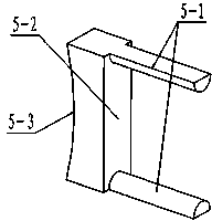
[0026] See Figure 1, figure 2 , image 3 , the present invention includes an adjusting arm assembly 9, a swing arm 10, a connecting arm 11, a rocking arm 6, an eccentric shaft 4 and a motor 13, the adjusting arm assembly 9 is articulated through the adjusting pin 2 and the connecting arm 11, and the connecting arm 11 is fixedly assembled with the swing arm 10, the swing arm 10 is assembled with the rocker arm 6, the two ends of the rocker arm 6 are respectively assembled with the valve 7 and the hydraulic tappet 8, and the eccentric shaft 4 is connected with the output shaft of the motor 13 , the motor 11 is installed on the engine block, and a set of eccentric wheels is set on the eccentric shaft 4, and its special feature is that it is also provided with a set of eccentric shaft adjustment plates 5, and the eccentric shaft adjustment plates 5 are reciprocated The bracket 5-1 is assembled with the eccentric shaft 4, and the first working surface 5-2 cooperating with the ecc...


PUM


Abstract

A mechanism for continuously adjusting engine valve lift is used for solving the problem of matching between the engine valve lift and engine running conditions. The mechanism comprises an adjusting arm assembly, a swinging arm, a connecting arm, a rocking arm, an eccentric shaft and a motor, the adjusting arm assembly is hinged to the connecting arm through an adjusting pin, the connecting arm is fixedly assembled with the swinging arm which is assembled with the rocking arm, two ends of the rocking arm are assembled with a valve and a hydraulic tappet respectively, the eccentric shaft is connected with a motor output shaft, and a set of eccentric wheel is arranged on the eccentric shaft. The mechanism is characterized in that a set of eccentric shaft adjusting plate is further arranged, the eccentric shaft adjusting plate is assembled with the eccentric shaft through a reciprocating motion support, a first working face matched with the eccentric wheel and a second working face matched with the adjusting arm assembly are arranged on the eccentric shaft adjusting plate, and the second working face is a circular-arc working face. By the mechanism, requirements on air inflow of an engine under different working conditions are met, the number of parts is reduced, and manufacturing cost of the parts is lowered.

Description

technical field [0001] The invention relates to an automobile engine, in particular to a valve lift continuous adjustment mechanism of an automobile engine gas distribution system, belonging to the technical field of internal combustion engines. Background technique [0002] The valve lift of the traditional engine gas distribution system is fixed, and the design of the valve lift is generally based on the intake air volume required by the engine under high-speed and heavy-load conditions, and it matches the shape of the profile curve of the valve cam. Due to the differences in the intake air demand of the engine under different operating conditions, the valve lift corresponding to the high-speed and heavy-load condition is large, and the valve lift corresponding to the low-speed and small-load condition is small. There is a phenomenon of excessive opening of the valve under load conditions. Although the gasoline engine can adjust the intake air volume by reducing the openin...

Claims


Application Information

Patent Timeline
IPC IPC(8): F01L13/00
Inventor 刘涛王航刘胜强胡佳佳尹吉张文龙
Owner GREAT WALL MOTOR CO LTD
Learn More