
Cam rotor pump for conveying high-viscosity medium

A cam rotor pump, high viscosity technology, applied in the field of rotor pump machinery, can solve the problems of poor versatility of conveying medium, low efficiency of conveying medium, increased maintenance cost, etc., and achieve the effect of benefiting lubrication, prolonging life and improving service life

Active Publication Date: 2014-03-26
烟台恒邦泵业有限公司
View PDF7 Cites 5 Cited by
  • Summary
  • Abstract
  • Description
  • Claims
  • Application Information

AI Technical Summary

Problems solved by technology

The transmission medium such as crude oil has high viscosity, sand and entrained gas. The use of the current conventional high-viscosity medium to transport heavy oil pumps has the problems of poor versatility of the transmission medium and low service life of wearing parts, which leads to inconvenient maintenance. , Increased maintenance costs, and low efficiency of conveying media due to gap leakage

Method used


Image

  • Cam rotor pump for conveying high-viscosity medium
  • Cam rotor pump for conveying high-viscosity medium
  • Cam rotor pump for conveying high-viscosity medium

Examples


Embodiment Construction

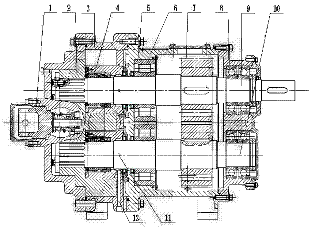
[0013] For better understanding and implementation, the present invention will be further described below in conjunction with the accompanying drawings: the lobe rotor pump for conveying high-viscosity medium includes a pump body 3, a safety valve 1 is provided at the front end of the pump body 3, and the pump body 3 is fixed to the gear box 6 connection, the pump body 3 and the gear box 6 are provided with a driving shaft 9 and a driven shaft 10 in parallel, and the driving shaft 9 and the driven shaft 10 are respectively provided with a rotor 2 and a synchronous gear 7, and the two rotors 2 are arranged perpendicularly to each other. The key is installed at the leftmost end of the two pump shafts, the two synchronous gears 7 mesh with each other, the driving shaft 9, the driven shaft 10 and the pump body 3 are sealed by the mechanical seal 4, the driving shaft 9, the driven shaft 10 and the gearbox The first bearing 5 of the cylindrical roller bearing and the second bearing 8...


PUM


Abstract

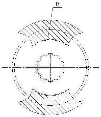
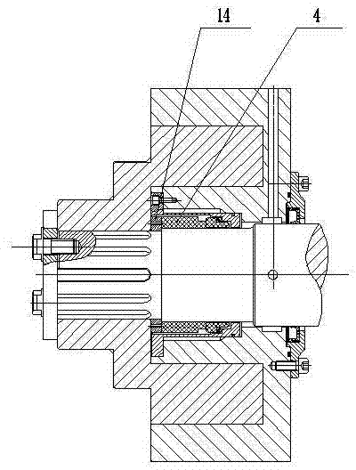
The invention provides a cam rotor pump for conveying a high-viscosity medium. The cam rotor pump comprises a pump body, wherein a safety valve is arranged at the front end of the pump body; the rear end of the pump body is fixedly connected with a gear box; a driving shaft and a driven shaft are arranged in the pump body and the gear box in the parallel manner; rotors and synchronous gears are respectively arranged on the driving shaft and the driven shaft; the two rotors are perpendicularly arranged at the leftmost ends of two pump shafts through keys; the two synchronous gears are meshed with each other; the driving shaft and the driven shaft are sealed with the pump body through mechanical seals; a first bearing and a second bearing are respectively arranged between the driving shaft and the gear box as well as the driven shaft and the gear box and are symmetric with each other; T-shaped slots are formed in the arc sides in fan-shaped blades of the rotors; a back-cooling flushing opening is formed in the upper end of the pump body, and an oil outlet is formed in the front side of the pump body; movable ring seats are arranged between the mechanical seals and the rotors. The mechanical seals of the cam rotor pump are convenient to assemble and disassemble; furthermore, even if the mechanical seals leak liquid, the bearing mediums cannot be polluted; the cam rotor pump is convenient to maintain, and the service lives of the mechanical seals are prolonged.

Description

technical field [0001] The invention belongs to the field of rotor pump machinery, in particular to a cam rotor pump for conveying high-viscosity medium. Background technique [0002] The rotor pump belongs to the positive displacement pump, and it is a power device used to transport medium and high viscosity liquid media in petroleum, chemical and other industries. The transmission medium such as crude oil has high viscosity, sand and entrained gas. The use of the current conventional high-viscosity medium to transport heavy oil pumps has the problems of poor versatility of the transmission medium and low service life of wearing parts, which leads to inconvenient maintenance. , The maintenance cost increases, and the transmission medium efficiency is low due to the problem of gap leakage. Contents of the invention [0003] In order to solve the above problems, the present invention provides a rotary lobe pump for conveying high-viscosity medium. [0004] The technical s...

Claims


Application Information

Patent Timeline
Patent Type & Authority Applications(China)
IPC IPC(8): F04C2/12F04C15/00
Inventor 王乐勤王炳波刘迎圆连加俤于豪杰姜林志
Owner 烟台恒邦泵业有限公司
Learn More