Drying drum

A drum and cylinder technology, applied in the field of dry-mixed mortar drying drums, can solve the problems of low drying efficiency, high energy consumption, insufficient contact time and the like

Active Publication Date: 2014-03-26
ZOOMLION HEAVY IND CO LTD
View PDF6 Cites 8 Cited by
  • Summary
  • Abstract
  • Description
  • Claims
  • Application Information

AI Technical Summary

Problems solved by technology

However, in this drying drum, the hot air flow entering from the inlet end has a certain axial velocity, so it is easier to pass through the cylinder 3 and then be discharged directly, resulting in insufficient contact time with the material, especially when the material is insufficient. under the circumstances
This makes the drying efficiency of the existing drying drum low and the energy consumption high, which cannot meet the requirements of energy saving and emission reduction

Method used


Image

  • Drying drum
  • Drying drum
  • Drying drum

Examples


Embodiment Construction

[0031] Specific embodiments of the present invention will be described in detail below in conjunction with the accompanying drawings. It should be understood that the specific embodiments described here are only used to illustrate and explain the present invention, and are not intended to limit the present invention.

[0032] In the present invention, in the case of no contrary description, the used orientation words such as "up, down, left and right" usually refer to the up, down, left and right shown in the accompanying drawings; "inside and outside" Refers to the inside and outside of the outline of each part itself.

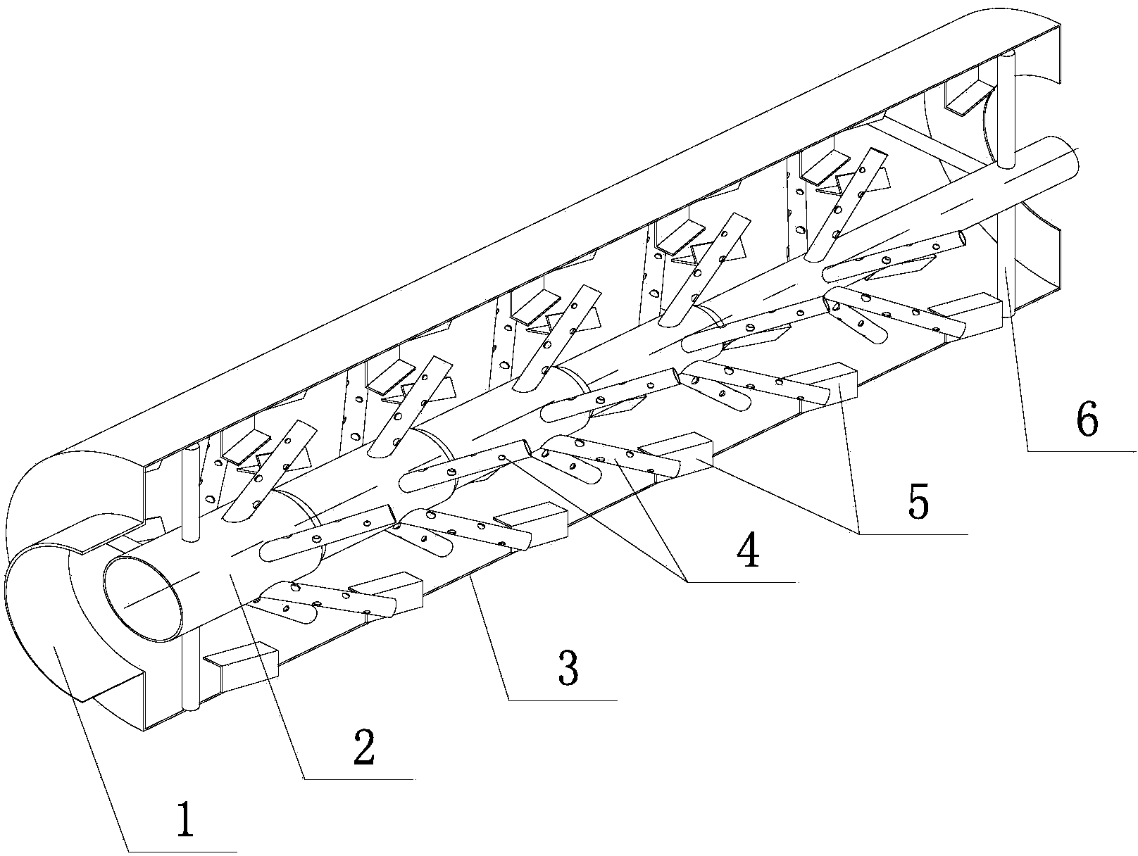
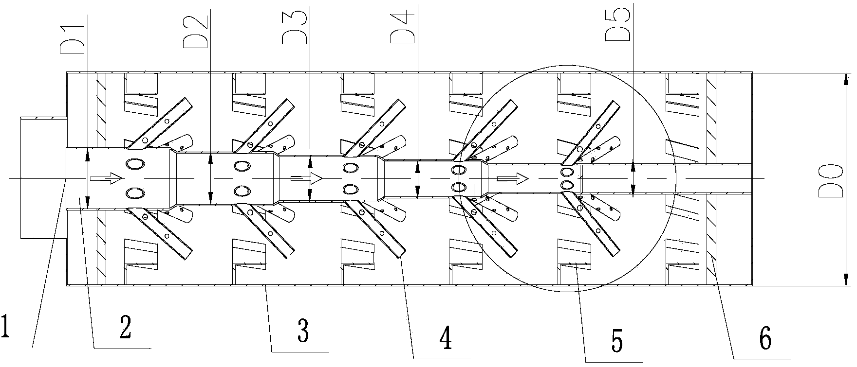
[0033] Such as figure 2 As shown, the present invention provides a drying drum, which includes a cylinder body 3, a main drainage pipe 2 and a drainage branch pipe 4 leading into a hot air flow, and the main drainage pipe 2 is axially connected from the inlet end 1 of the cylinder body 3. Extending into the inner cavity of the cylinder body 3 , the drainag...


PUM


Abstract

The invention discloses a drying drum which comprises a drum body (3), a main drainage pipe (2) and branch drainage pipes (4), wherein hot airflow is input into the main drainage pipe (2) and the branch drainage pipes (4). The main drainage pipe axially extends into an inner cavity of the drum body from an inlet end (1) of the drum body, the branch drainage pipes are communicated with the main drainage pipe and used for draining hot airflow in the main drainage pipe to the inner cavity, and therefore turbulent flow is formed. When the hot airflow is input into the inlet end, a major part of the hot airflow enters the main drainage pipe, a small part of the hot airflow enters the space formed between the main drainage pipe and the inner wall of the drum body, and the hot airflow in the main drainage pipe flows everywhere in the inner cavity of the drum body through the branch drainage pipes which extend in the radial direction. The airflow which flows into the branch drainage pipes from the main drainage pipe and then is sprayed out has the higher speed, speed difference exists between the airflow and the hot airflow directly flowing into the inner cavity, a flow field in the inner cavity of the drum body generates strong disturbance due to the speed difference and the rotation of the drum, and turbulence intensity is enhanced, so that the good heat convection effect is good, and the energy consumption use ratio is improved.

Description

technical field [0001] The invention relates to a drying drum, in particular to a dry-mixed mortar drying drum with a blowing enhanced heat exchange device. Background technique [0002] in such as figure 1 In the common dry-mixed mortar drying drum shown, the rotation of the cylinder 3 mainly drives the lifting blade 5 (or lifting plate) in the cylinder 3 to lift and sprinkle the material, and at the entrance of the cylinder 3 When the hot air flow is passed through the end, the heat exchange between the material and the hot air flow is realized, thereby drying the material. Among them, in order to improve the thermal efficiency of the drying drum and obtain a better drying effect, it is mainly through the rational design of the structure of the material lifting blade 5 and the use of a combined material lifting blade structure to make the material form a continuous material curtain and prolong the time of the material in the air. Thereby enhancing the heat exchange effec...

Claims


Application Information

Patent Timeline
Patent Type & Authority Applications(China)
IPC IPC(8): F26B25/16F26B21/00
Inventor 张斌万军尹友中黄玮张劲
Owner ZOOMLION HEAVY IND CO LTD
Why Eureka
Try Eureka