Image fusion device and method based on period diffraction correlated imaging

An image fusion and correlation imaging technology, applied in the field of correlation imaging, can solve the problems of complex calculation and poor anti-interference, and achieve the effect of good anti-interference, high flexibility and reducing the amount of calculation.

Inactive Publication Date: 2014-03-26
SHANGHAI JIAO TONG UNIV
View PDF2 Cites 18 Cited by
  • Summary
  • Abstract
  • Description
  • Claims
  • Application Information

AI Technical Summary

Problems solved by technology

The calculation of the traditional image fusion algorithm is mainly realized by software algorithm, the calcul

Method used


Image

  • Image fusion device and method based on period diffraction correlated imaging
  • Image fusion device and method based on period diffraction correlated imaging
  • Image fusion device and method based on period diffraction correlated imaging

Examples


Embodiment 1

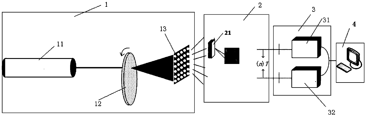
[0042] Such as figure 1 As shown, there is one target object, and the image fusion device based on periodic diffraction correlation imaging includes a pseudothermal light source module 1 , a transmission module 2 , a detection module 3 and a post-processing module 4 . The transmission module 2 includes a target object 21, a signal path and a reference path. The detection module 3 is arranged at the far end, including a first detector 31 and a second detector 32, wherein the pseudothermal light source module 1 emits a light beam, and a part of the light beam is directly received by the second detector 32 through space transmission; the other part irradiates the target object 21, the transmitted light beam of the target object 21 is received by the first detector 31 after transmission; the output of the second detector 32 is used as reference information, the output of the first detector 31 is used as target object information, the output of the second detector 32 and The outpu...

Embodiment 2

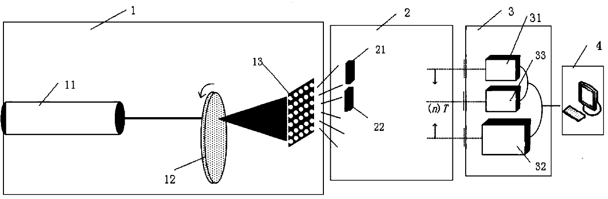
[0056] Such as figure 2 As shown, the transmission module 2 includes a first target object 21 and a second target object 22, and the detector 3 includes three detectors, as figure 2 As shown, the image fusion device based on periodic diffraction correlation imaging includes a pseudothermal light source module 1 , a transmission module 2 , a detection module 3 and a post-processing module 4 . The transmission module 2 includes a signal path and a reference path. The detection module 3 is arranged at the far end and includes a first detector 31, a second detector 32 and a third detector 33, wherein the pseudothermal light source module 1 emits a light beam, and a part of the light beam is directly transmitted by the second detector through space transmission. 32 to receive; the other part illuminates the first target object 21 and the second target object 22, and the transmitted light beams of the two target objects are respectively received by the first detector 31 and the t...


PUM

PropertyMeasurementUnit
Wavelengthaaaaaaaaaa
Diameteraaaaaaaaaa

Abstract

The invention discloses an image fusion device and method based on period diffraction correlated imaging. The image fusion device comprises a fake thermal light source module, a transmission module, a detection module and a later-period solving module, wherein the transmission module comprises a signal path and a reference path, and the detection module comprises a first detector and a second detector. The image fusion device method comprises the steps that the fake thermal light source module gives out a light beam, part of the light beam is directly received by the second detector through space transmission, the other part of the light beam irradiates a target object, the light beam which penetrates through the target object is received by the first detector through transmission, output of the second detector and output of the first detector are sent to the later-period solving module, and the later-period solving module recovers an image of the target object through correlated calculation. According to the image fusion device and method based on period diffraction correlated imaging, calculation is easy and convenient, the cost is low, flexibility is high, and anti-interference performance is good.

Description

technical field [0001] The present invention relates to the technical field of correlation imaging, in particular to an image fusion device and method based on periodic diffraction correlation imaging. Background technique [0002] Imaging is the most basic way for human beings to obtain external information, and it is also the basis for human beings to judge and respond to the external environment. The existing correlative imaging technology is very mature, and can get good results from microscopic imaging to astronomical imaging. In traditional correlative imaging, the pseudothermal light is divided into two beams by a beam splitter, and the two spatially correlated lights travel along different paths, and only one of them is irradiated on the target object to be imaged, and the light passing through the target object Collected with a barrel detector, known as the signal path. The other path of light is collected by a charge-coupled device image sensor (CCD) after propag...

Claims


Application Information

Patent Timeline
IPC IPC(8): G01J5/00
Inventor 孙梦洁石剑虹曾贵华
Owner SHANGHAI JIAO TONG UNIV
Why Eureka
Try Eureka