Current collecting device on power transmission line

A technology of transmission lines and collection devices, applied in the field of electric power equipment, to achieve the effect of saving low-voltage DC power

Inactive Publication Date: 2014-03-26
浙江华采科技有限公司
View PDF7 Cites 6 Cited by
  • Summary
  • Abstract
  • Description
  • Claims
  • Application Information

AI Technical Summary

Problems solved by technology

But this acquisition device also has the disadvantages of the above-mentioned power supply

Method used


Image

  • Current collecting device on power transmission line

Examples


Embodiment Construction

[0018] The following are specific embodiments of the present invention and in conjunction with the accompanying drawings, the technical solutions of the present invention are further described, but the present invention is not limited to these embodiments.

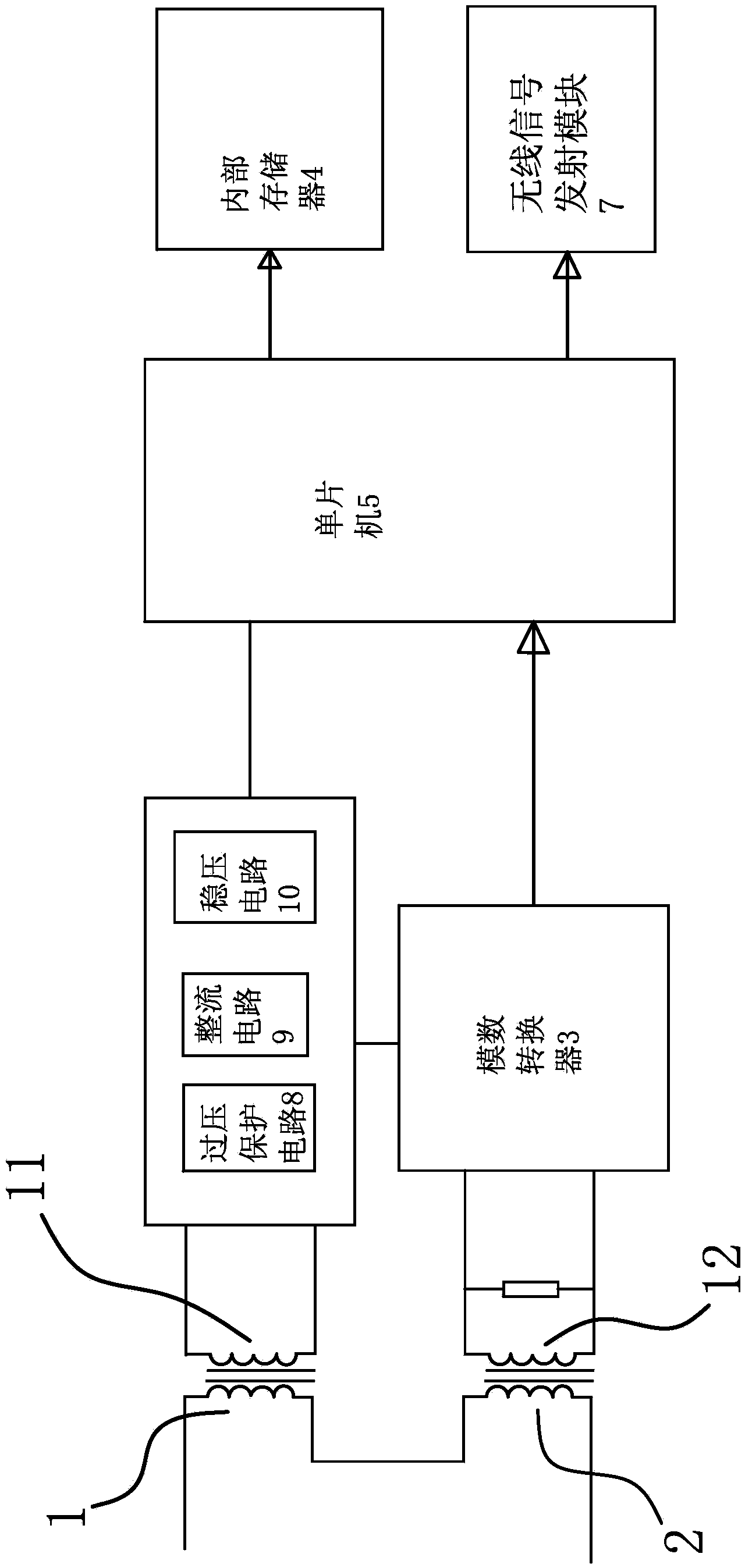
[0019] like figure 1 As shown, the acquisition device includes a power-taking mutual induction coil 1, a sampling mutual induction coil 2, an analog-to-digital conversion circuit 3, an internal memory 4, a single-chip microcomputer 5 and a power supply arrangement unit 6, and the power-taking mutual induction coil 1 and the sampling mutual induction coil 2 are independent of each other. The secondary output winding 11 on the electric mutual induction coil 1 is electrically connected with the power arrangement unit 6. The power arrangement unit 6 can rectify, stabilize and protect the current output by the secondary output winding 11. The power arrangement unit 6 will arrange The final current is delivered to the single-chi...


PUM


Abstract

The invention provides a current collecting device on a power transmission line, and belongs to the technical field of power equipment. The current collecting device solves the technical problem that in the prior art, an extra power supply is needed for power supply. The current collecting device comprises a power taking mutual inductance coil, a sampling mutual inductance coil, an analog-digital conversion circuit, an internal memory, a single chip microcomputer, a wireless signal transmitting module and a power supply arranging unit, wherein the power taking mutual inductance coil and the sampling mutual inductance coil are mutually independent, a secondary output winding on the power taking mutual inductance coil is in electric connection with the power supply arranging unit, and the power supply arranging unit can carry out rectification, voltage stabilization and over-voltage protection on currents output by the secondary output winding. The current collecting device has the function of directly obtaining induction currents from the power transmission line and an extra low-voltage direct-current power supply is omitted; the magnitude of voltage on the power transmission line cannot influence operation of the collecting device, and the function of being free of being influenced by the magnitude of the voltage is achieved.

Description

technical field [0001] The invention belongs to the technical field of electric power equipment, and relates to a current collection device on a power transmission line. Background technique [0002] In order to realize automatic management in the power transmission and distribution link, it is necessary to measure the operating parameters of the power line, especially the measurement of the line current. [0003] The electronic unit of the measurement device needs power supply. At present, the measurement device on the medium and high voltage line generally adopts PT power supply, auxiliary low-voltage power supply, solar power supply and optical fiber power supply. The first two methods need to consider high-voltage insulation in the design of the device, so the device is relatively large and inconvenient to install; solar power supply has the problems of high cost and complicated installation; optical fiber power supply requires the installation of optical fibers, and the...

Claims


Application Information

Patent Timeline
Patent Type & Authority Applications(China)
IPC IPC(8): G01R19/25
Inventor 高少军郑国鑫周泉黎景伦李方庚
Owner 浙江华采科技有限公司
Why Eureka
Try Eureka