A conveying roller table used in a fully automatic factory test system for motors

A factory test and conveying roller technology, which is applied in the field of motor manufacturing, can solve the problems of the lack of protection system of the roller line system, the out-of-synchronization of the running speed of the roller line, and endanger the personal safety of operators, etc. The effect of high efficiency and high degree of automation

Active Publication Date: 2016-08-31
SHANGHAI MOTOR SYST ENERGY SAVING ENG TECH RES CENT +1
View PDF8 Cites 0 Cited by
  • Summary
  • Abstract
  • Description
  • Claims
  • Application Information

AI Technical Summary

Problems solved by technology

However, since the traditional roller line does not have a power transmission system that follows the movement of the roller line, if a rhythmic test method is to be realized, it needs to be manually wired multiple times according to different test items, and each work section must be arranged manually, otherwise it is still impossible to achieve Efficient testing; moreover, because the traditional roller table line has no position status feedback system, it may cause the phenomenon that the running speed of the roller table line is not synchronized with the output of the test system, and the operator may cause abnormal output due to the asynchronous phenomenon when wiring; at the same time, The traditional roller line system also lacks a corresponding protection system, which is very likely to endanger the personal safety of operators
Moreover, since the traditional roller table line system does not have a protection system for the tested motor, during the test process, if an abnormal situation occurs in one motor, it will affect the motors being tested in other working sections, and the whole test process will be stagnant. Seriously affect production efficiency

Method used


Image

  • A conveying roller table used in a fully automatic factory test system for motors
  • A conveying roller table used in a fully automatic factory test system for motors

Examples


Embodiment Construction

[0018] In order to make the present invention more comprehensible, preferred embodiments are described in detail below with accompanying drawings.

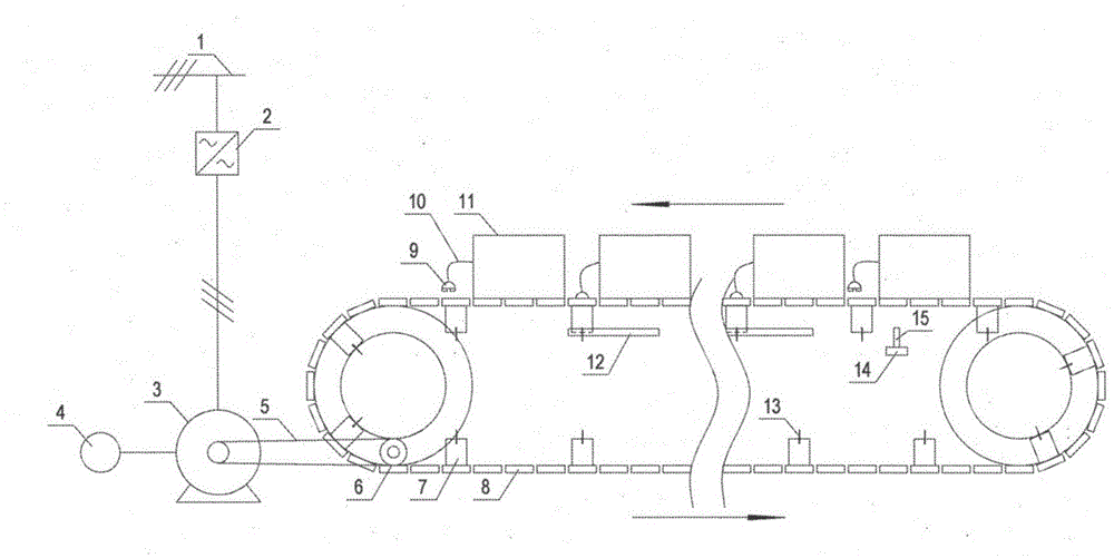
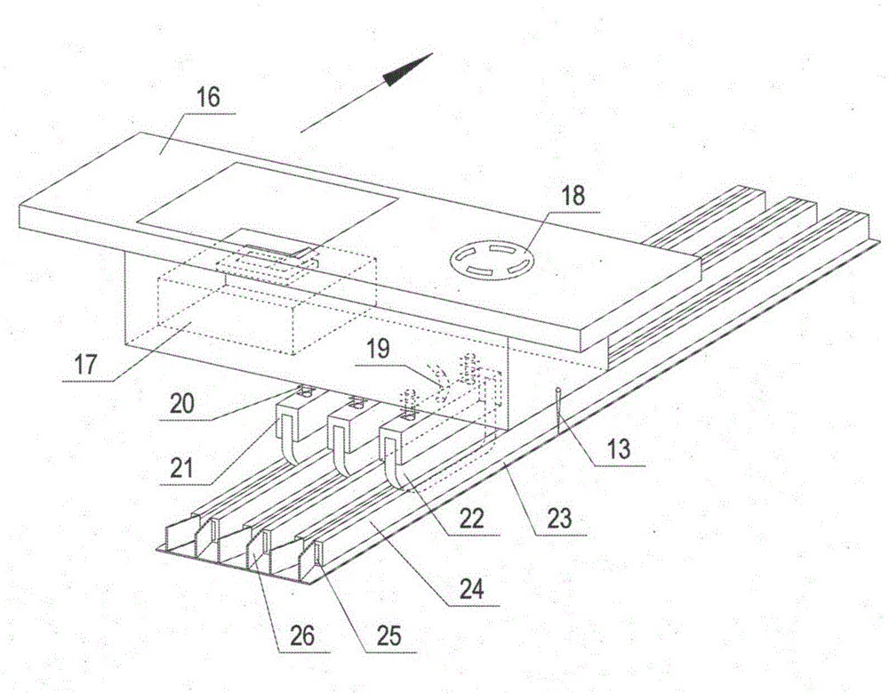
[0019] Such as figure 1 As shown, a conveyor roller table used in a fully automatic factory test system for motors provided by the present invention includes: a power bus 1, a drive frequency converter 2, a drive motor 3, a photoelectric encoder 4, a drive belt 5, and a roller table line drive wheel 6. Power transmission conveying board 7, ordinary conveying board 8, plug 9, motor power transmission cable 10, tested motor 11, bronze slot 12, position probe 13, photoelectric switch bracket 14, photoelectric switch 15.

[0020] The crawler structure is connected by the power transmission conveying plate 7 and the ordinary conveying plate 8. The drive unit drives the crawler structure to run in a cycle. N ordinary conveying plates 8 connected end to end and a power transmission conveying plate 7 form a motor station. , the length of...


PUM


Abstract

The invention provides a conveying roller way used for a motor full-automatic predelivery test system. The conveying roller way used for the motor full-automatic predelivery test system is characterized in that a crawler-type structure formed by connecting electricity transmission conveying boards and common conveying boards is included, the crawler-type structure is driven to carry out cycle operation through a drive unit, a motor working position is formed by N common conveying boards and one electricity transmission conveying board in an end to end mode, at least one motor to be tested is arranged on each motor working position, the power input end of each motor to be tested is connected with the electricity transmission conveying board when tested, at least one section of copper plate groove is formed in the inner side of the crawler-type structure, each section of copper plate groove corresponds to a working section, and when the electricity transmission conveying boards run to the copper plate grooves and make contact with the copper plate grooves, the motor full-automatic predelivery test system carries out electricity transmission control over motors to be tested through the copper plate grooves and the electricity transmission conveying boards. The conveying roller way used for the motor full-automatic predelivery test system has the advantages of being simple in structure, stable in running, high in reliability, capable of adjusting operation speed freely and good in effect, and effectively reducing number of needed operating staff.

Description

technical field [0001] The invention relates to a motor conveying roller table, in particular to a conveying roller table used in a fully automatic factory test system for a motor, and belongs to the technical field of motor manufacturing. Background technique [0002] The motor factory test equipment is one of the necessary production equipment in the motor manufacturing process. Generally, the factory test system has low test efficiency and is difficult to adapt to the production rhythm of the production line. However, through the rhythmic test method, the test area is divided into several working sections. One working section completes one test item. When the motor completes the current working section, it is transported to the next working section for the next test item. In this way, multiple motors can be tested at the same time, which greatly improves the testing efficiency of the motor. However, since the traditional roller line does not have a power transmission syst...

Claims


Application Information

Patent Timeline
Patent Type & Authority Patents(China)
IPC IPC(8): G01R31/34
Inventor 陈伟华王传军童陟嵩金惟伟韩宝江
Owner SHANGHAI MOTOR SYST ENERGY SAVING ENG TECH RES CENT
Why Eureka
Try Eureka