Through-the-wall radar imaging method

A technology of through-wall radar and radar imaging, applied in the field of radar, can solve the problems such as inability to effectively compensate for the influence of the imaging position and accuracy of the wall, low imaging speed, and complicated algorithms, achieving a small amount of calculation, taking into account calculation efficiency, and ensuring imaging. The effect of precision

Active Publication Date: 2014-03-26
INST OF ELECTRONICS CHINESE ACAD OF SCI
View PDF7 Cites 8 Cited by
  • Summary
  • Abstract
  • Description
  • Claims
  • Application Information

AI Technical Summary

Problems solved by technology

[0004] In the process of realizing the present invention, the applicant found that the prior art through-wall radar imaging method cannot effectively compensate the influence of the wall on the imaging position and accuracy
In addition, due to the cumbersome algorithm, the imaging speed is low and the timeliness is poor

Method used


Image

  • Through-the-wall radar imaging method
  • Through-the-wall radar imaging method
  • Through-the-wall radar imaging method

Examples


Embodiment 1

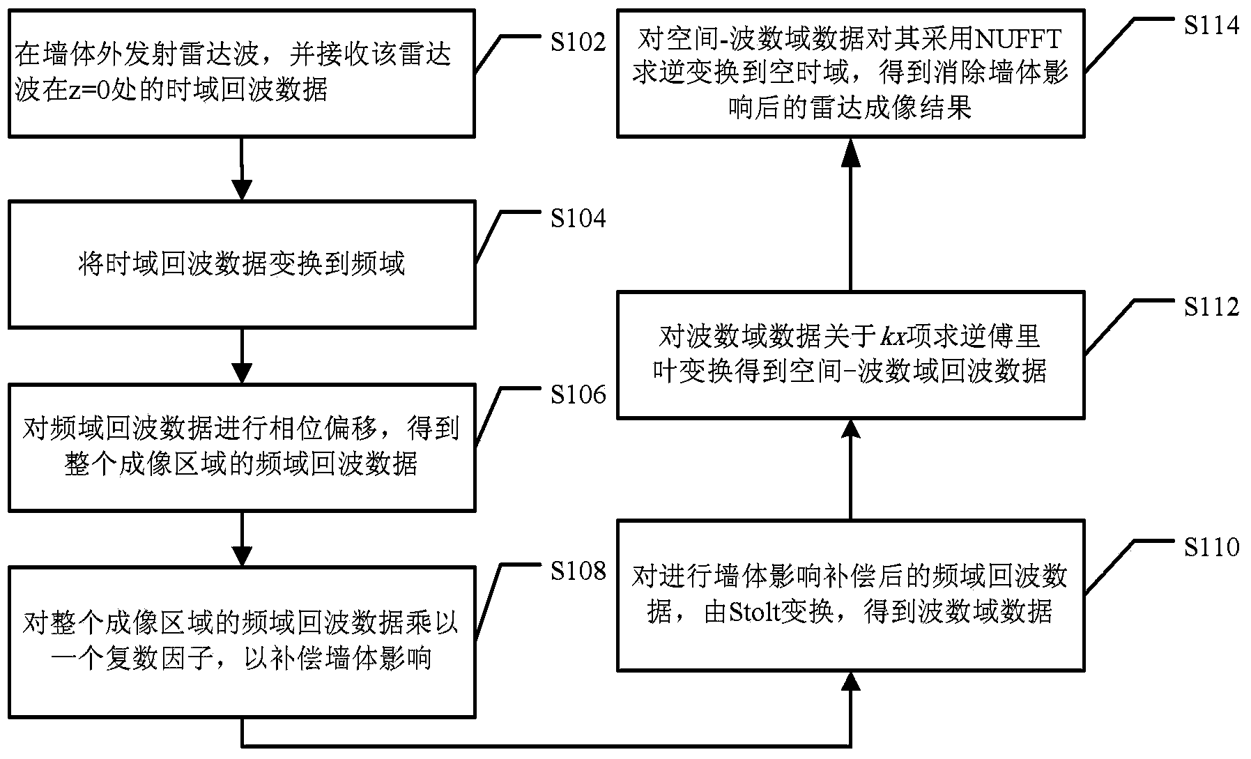
[0026] In the first exemplary embodiment of the present invention, a through-wall radar imaging method for three-layer media in two-dimensional space is provided. Please refer to schematic diagram 1, the through-wall radar imaging method in this embodiment includes:

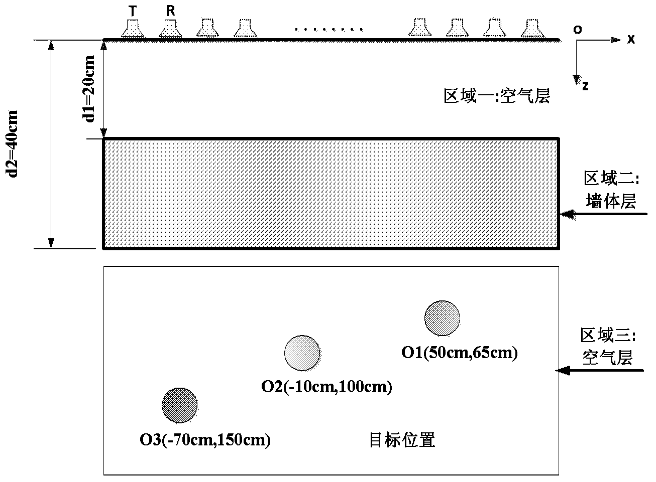
[0027] Step S102, launch the radar wave outside the wall, and receive the time-domain echo data d′ of the radar wave at the measurement line z=0 1 (x,z=0,t);

[0028] As shown in Figure 1, T is the radar device for transmitting electromagnetic waves, and R is the radar device for receiving time-domain echo data, both of which are located along the external surface of the wall. A radar device receiving at least time domain echo data is moved along a survey line parallel to the outer surface of the wall. Among them, x and z are the two coordinate axes of the two-dimensional space. The positive direction of the x-coordinate axis is the outward direction along the measurement line, and the positive direction of th...

Embodiment 2

[0048] In the second exemplary embodiment of the present invention, a through-wall radar imaging method for three-layer media in three-dimensional space is provided. Please refer to the instructions Figure 5A In this embodiment, the through-wall radar imaging method includes:

[0049] Step S202, use the radar to emit electromagnetic waves outside the wall, and obtain the time-domain echo data d′ of the electromagnetic waves at the measurement surface z=0 2 (x,y,z=0,t);

[0050] as indicated Figure 5A As shown, T is a radar device for transmitting electromagnetic waves, and R is a radar device for receiving time-domain echo data, both of which are located along the outer surface of the wall. A radar device receiving at least time-domain echo data is moved within a measurement plane parallel to the outer surface of the wall. Wherein, x, y and z are three coordinate axes of the three-dimensional space. The positive direction of the x-coordinate axis is the outward directio...


PUM


Abstract

The invention provides a through-the-wall radar imaging method. According to the method, in a radar imaging processing process, spectral data is multiplied by a wall compensation factor; the compensation factor uses an accurate physical model and takes interaction between an electromagnetic wave and a wall into account; and accordingly, an impact of the wall on an imaging position is eliminated, and the imaging accuracy is ensured. In addition, since the elimination of the impact of the wall is in a frequency domain and only multiplication is used, and compensation factor calculation does not need solving a nonlinear equation, the calculation amount is quite small.

Description

technical field [0001] The invention relates to the technical field of radar, in particular to a method for imaging through-wall radar. Background technique [0002] Through-Wall Imaging (TWI) is mainly used to detect or locate targets hidden behind walls or obstacles. In recent years, through-wall imaging has been widely used in life detection, anti-terrorism and stability maintenance, and disaster rescue. These applications put forward objective requirements for the accuracy and efficiency of through-wall imaging algorithms. Therefore, the research on efficient and accurate through-wall imaging algorithm has important application value and has become a research hotspot in this field. [0003] Through-wall imaging is formed by emitting electromagnetic waves and processing the received echo data. Electromagnetic waves are refracted and scattered multiple times as they penetrate walls. This interaction between the electromagnetic wave and the wall will cause deviations in ...

Claims


Application Information

Patent Timeline
IPC IPC(8): G01S13/89
CPCG01S7/2928G01S13/888G01S13/90
Inventor 张晓娟王友成张鹏
Owner INST OF ELECTRONICS CHINESE ACAD OF SCI
Why Eureka
Try Eureka