Liquid crystal panel and manufacturing method thereof

A technology for a liquid crystal panel and a manufacturing method, which is applied in nonlinear optics, instruments, optics, etc., can solve the problems of light leakage, easy deformation, and displacement of pads, etc. of the liquid crystal panel, so as to prevent light leakage, solve the problem of light leakage, and form a method. simple effect

Inactive Publication Date: 2014-03-26
TCL CHINA STAR OPTOELECTRONICS TECH CO LTD
View PDF5 Cites 10 Cited by
  • Summary
  • Abstract
  • Description
  • Claims
  • Application Information

AI Technical Summary

Problems solved by technology

However, the color filter substrate, as the outer surface of the liquid crystal panel, is prone to deformation when it is under pressure, and the pads will also be displaced to a certain extent, resulting in light leakage in the liquid crystal panel.

Method used


Image

  • Liquid crystal panel and manufacturing method thereof
  • Liquid crystal panel and manufacturing method thereof
  • Liquid crystal panel and manufacturing method thereof

Examples


Embodiment Construction

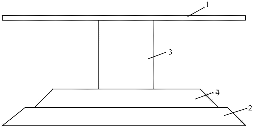
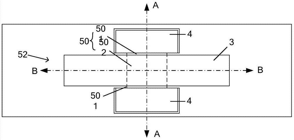
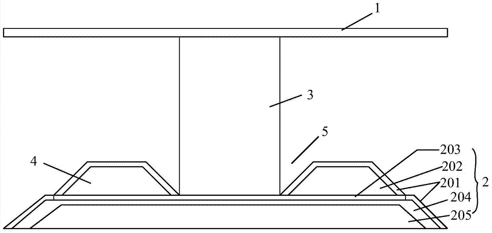
[0020] refer to figure 2 with image 3 As shown, the present invention provides a structure of a liquid crystal panel, which includes a first substrate 1 and a second substrate 2, and a support column 3 and a spacer arranged on the opposite substrate are arranged between the two substrates. 4. Between the support column 3 and the spacer 4, there are stoppers 5 for positioning in different directions, so as to prevent relative movement of the substrate. The spacer 4 is arranged above the second base plate 2, and is used to limit and fix the support column 3. The first base plate 1 is supported by the support column 3, and is supported on the first base plate 1 by the support column 3. A certain box thickness is formed between the first substrate 1 and the second substrate 2, and plays the role of supporting the box thickness when the first substrate 1 is under pressure and the box thickness decreases.

[0021] The limiter 5 is arranged in different directions of the spacer 4...


PUM


Abstract

The invention provides a liquid crystal panel which comprises a first substrate and a second substrate. A supporting column is arranged between the two substrates, and an underlay is arranged on the substrate on the opposite side. Limit parts are arranged between the supporting column and the underlay and used for limiting in different directions so that relative motion between the substrates can be prevented from happening. The limit parts in at least two directions are arranged on the underlay and mutually matched with the supporting column so that limit can be performed on the supporting column in the different directions, then the two substrates are prevented from shifting front and back and left and right, and the effect of preventing light leakage is achieved. The limit parts are combined in various modes, pairs of grooves or protrusions are arranged on the two side edges of the supporting column so that the side positions of the supporting columns can be limited, meanwhile, a groove or a protrusion can be arranged in the middle of the underlay and mutually fastened with the supporting column, middle limiting of the supporting column is strengthened, and therefore the purpose of limiting a supporting base in a multi-point and multi-position mode is achieved. The invention further provides a manufacturing method of the liquid crystal panel.

Description

technical field [0001] The invention relates to a liquid crystal panel and a manufacturing method thereof, in particular to a liquid crystal panel and a manufacturing method thereof capable of limiting and adjusting the spacer therein. Background technique [0002] In existing LCD screens, refer to figure 1 As shown, there are generally a color filter substrate, an array substrate, and a spacer between the two. A multilayer film is formed on the color filter substrate and the array substrate through a coating process, and the spacer is placed in the liquid crystal panel. It plays the role of supporting the thickness of the liquid crystal box, so that the middle part is suspended. However, the color filter substrate, as the outer surface of the liquid crystal panel, is prone to deformation when it is under pressure, so that the pads will also be displaced to a certain extent, resulting in light leakage in the liquid crystal panel. Contents of the invention [0003] Based ...

Claims


Application Information

Patent Timeline
Patent Type & Authority Applications(China)
IPC IPC(8): G02F1/1339G02F1/1333
CPCG02F1/13394
Inventor 付延峰
Owner TCL CHINA STAR OPTOELECTRONICS TECH CO LTD
Why Eureka
Try Eureka