
Single-wire transmission circuit and method of LED (Light-Emitting Diode) display module single-point correction data

A technology of LED display and display module, applied in static indicators, instruments, etc., can solve the problems of affecting the appearance of the cabinet and increasing the difficulty of wiring, so as to make up for the difference in brightness and chromaticity, reduce maintenance time, and restore use as soon as possible Effect

Active Publication Date: 2014-03-26
YAHAM OPTOELECTRONICS CO LTD
View PDF6 Cites 28 Cited by
  • Summary
  • Abstract
  • Description
  • Claims
  • Application Information

AI Technical Summary

Problems solved by technology

The early LED display single-point calibration technology has no online position recognition function, and the calibration data is stored in the PC. After the calibration data of the entire screen is produced, the position of each LED display module cannot be changed. If it is changed, it needs to be recreated. Calibration data for the whole screen
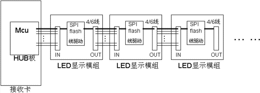
The existing solution is to set a serial peripheral interface (Serial Peripheral Interface, abbreviated as SPI) memory and a corresponding line driver IC in the LED display module, such as figure 2 As shown, the parameters after point-by-point correction, that is, the correction data, are stored in the SPI memory, so that the correction data of the LED display module changes with the LED display module, and the online position recognition function is added. After the LED display is put into operation, it is also The correction parameters can be modified to compensate for the influence of LED aging on the display effect and improve the service life of the LED display. However, the control signals required by the SPI memory include clock signal CLK, serial data input signal SDI, serial data output signal SDO and The chip selection signal CS makes each LED display module need to be connected with 4 control wires. The corresponding 4 / 6 wire mode not only increases the difficulty of wiring, but also affects the aesthetics of the cabinet

Method used


Image

  • Single-wire transmission circuit and method of LED (Light-Emitting Diode) display module single-point correction data
  • Single-wire transmission circuit and method of LED (Light-Emitting Diode) display module single-point correction data
  • Single-wire transmission circuit and method of LED (Light-Emitting Diode) display module single-point correction data

Examples


Embodiment Construction

[0029] The present invention will be described below in combination with specific embodiments and with reference to the accompanying drawings.

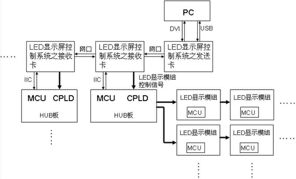
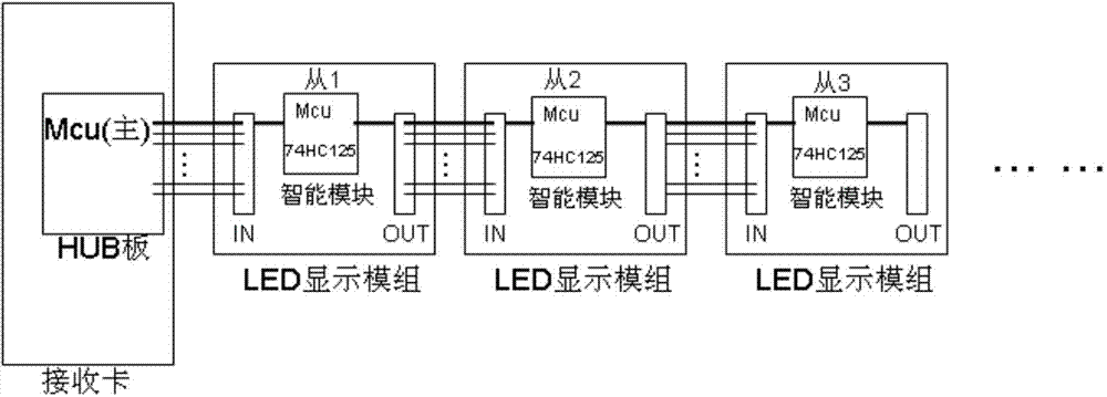
[0030] Such as image 3 , 4 The single-line transmission circuit of the single-point correction data of the LED display module shown includes the LED display module and the HUB board with the main MCU of model STC11L08XE. The LED display module includes LED and constant current driver IC, the HUB board and the LED The receiving card of the display control system is connected, and the receiving card of the LED display control system provides control signals that can be displayed normally to the LED display module. The HUB board includes the main MCU and CPLD. The function of the main MCU is to parse from the I 2 The command of the C bus identifies the corresponding slave MCU, and transmits the single-point calibration data with the slave MCU through the serial port. The function of the CPLD is to control the direction of data flow, s...


PUM


Abstract

The invention discloses a single-wire transmission circuit and a single-wire transmission method of LED (Light-Emitting Diode) display module single-point correction data, wherein the circuit is provided with an intelligent module which includes a tri-state output buffer door and a slave MCU (Microprogrammed Control Unit) with own EEPROM (Electrically Erasable Programmable Read-Only Memory). A HUB board on a receiving card of an LED screen control system is in single-sire communication with the intelligent module on the LED display module through a serial port, the single-point correction sate of the display module is read from the EEPROM in the MCU on the intelligent module, the receiving card controls the display of the LED screen according to the correction data and enables the display brightness of LED screen to be uniform so as to remedy the defect that LED chips have brightness and chrominance differences, and the installation position of the LED display module as well as the screen position can be freely changed, so that the installation of the LED display module and screen is more flexible. Maintainers are not needed to go to the site to re-collect the screen of the new LED display module by a professional camera and re-generate the correction data, and thus the LED screen is more convenient to maintain.

Description

technical field [0001] The invention relates to an LED display screen, in particular to a single-line transmission circuit and method for single-point correction data of an LED display module. Background technique [0002] Such as figure 1 The sending card of the LED display control system in the shown LED display control system communicates with the PC through the USB interface, and after obtaining the image data from the DVI interface of the PC, it outputs to at least one receiving card of the LED display control system. The receiving card of each LED display control system passes the I 2 The C interface communicates with the HUB, the main MCU on the hub board, and provides the acquired image data to the LED display module through the HUB board to provide control signals that can display image information normally, so that the LED display screen displays images. Due to the limitations of the light emitting diode (Light Emitting Diode, abbreviated as LED) chip manufacturi...

Claims


Application Information

Patent Timeline
IPC IPC(8): G09G3/32
Inventor 王占明钟涛卢青松
Owner YAHAM OPTOELECTRONICS CO LTD
Learn More