Magnetic assembly and winding frame thereof

A technology of magnetic components and bobbins, applied in electrical components, transformer/inductor cores, transformer/inductor components, etc., can solve the problem of occupying the available space of bobbins

Active Publication Date: 2014-03-26
DELTA ELECTRONICS INC
View PDF4 Cites 3 Cited by
  • Summary
  • Abstract
  • Description
  • Claims
  • Application Information

AI Technical Summary

Problems solved by technology

And because the blade has a certain thickness, it will i

Method used


Image

  • Magnetic assembly and winding frame thereof
  • Magnetic assembly and winding frame thereof
  • Magnetic assembly and winding frame thereof

Examples


Embodiment Construction

[0038] A number of embodiments of the present invention will be disclosed below with the accompanying drawings. For the sake of clarity, many practical details will be described together in the following description. However, those skilled in the art should appreciate that in some embodiments of the present invention, these practical details are not necessary and thus should not be used to limit the present invention. In addition, for the sake of simplifying the drawings, some existing conventional structures and components will be shown in a simple and schematic manner in the drawings.

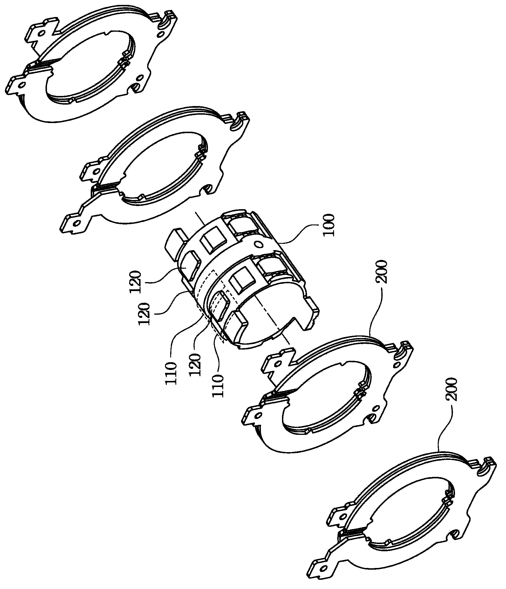
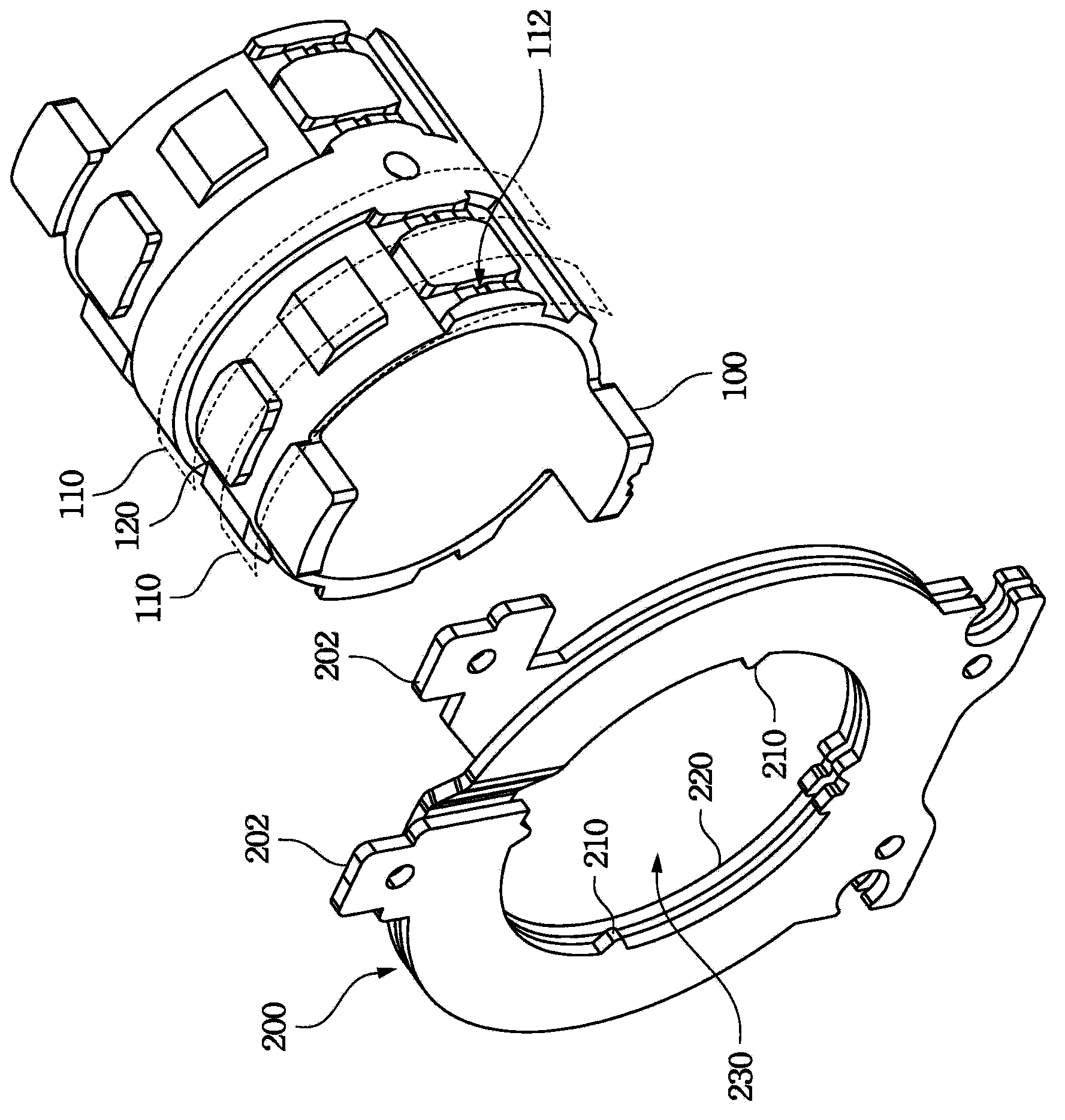
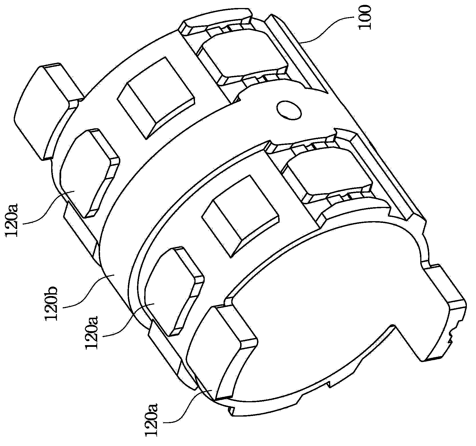
[0039] figure 1 An exploded view showing a bobbin according to an embodiment of the present invention. The winding frame of this embodiment may include a winding sleeve 100 and a plurality of conductive sheet groups 200 . The winding sleeve 100 has a plurality of limiting slots 110 and a plurality of winding bases 120 . The winding bases 120 are generally arranged on the outer surface of t...


PUM


Abstract

The invention provides a magnetic assembly and a winding frame of the magnetic assembly. The winding frame applied to the magnetic assembly comprises a winding sleeve and a plurality of conducting piece sets. The winding sleeve is provided with a plurality of limiting grooves and a plurality of winding bases. The winding bases are roughly arrayed on the outer surface of the winding sleeve in the axial direction of the winding sleeve, and the limiting grooves are isolated from the winding bases. The conducting piece sets are sleeved with the limiting grooves and abut against the winding bases.

Description

technical field [0001] The invention relates to a magnetic assembly and its winding frame, and in particular to a bladeless magnetic assembly and its winding frame. Background technique [0002] In the modern life full of various electronic devices, the transformer is an indispensable electronic component, which is used to adjust different voltages to make the voltage reach the applicable range of electrical equipment. [0003] The structure of the transformer mainly includes a winding frame, a magnetic core group, a primary winding and a secondary winding. Both the primary winding and the secondary winding are sleeved on the winding frame. When the input voltage is transmitted to the primary winding, the magnetic core group will produce electromagnetic action, so that the output voltage of the secondary winding, and through the difference in the number of turns of the primary winding and the secondary winding, the output voltage is different from the input voltage, thus ac...

Claims


Application Information

Patent Timeline
IPC IPC(8): H01F27/30H01F27/00H01F27/26
Inventor 林骅笙吴一凡李昱洁张治良邓经宪洪楀量
Owner DELTA ELECTRONICS INC
Why Eureka
Try Eureka