An ion implanter wide beam uniformity adjustment device

A technology for ion implanters and adjustment devices, which is applied in the direction of discharge tubes, electrical components, circuits, etc., can solve the problems of difficult control of wide beam uniformity, shorten the length of transmission optical path, and reduce transmission distance, so as to improve beam quality, beam The flow uniformity control is convenient and fast, and the effect of meeting the uniformity requirements

Active Publication Date: 2016-03-09
BEIJING SHUOKE ZHONGKEXIN ELECTRONICS EQUIP CO LTD
View PDF9 Cites 0 Cited by
  • Summary
  • Abstract
  • Description
  • Claims
  • Application Information

AI Technical Summary

Problems solved by technology

[0005] In order to solve the problem that the uniformity of the wide beam is difficult to control, this invention combines the successful experience and technical advantages of developing semiconductor ion implanters, utilizes the original ion optical system, and reduces the optical components as much as possible under the premise of ensuring the functional requirements of the whole machine, so as to shorten the The length of the transmission optical path reduces the transmission distance, thereby improving the transmission efficiency of the system; on the premise of solving the wide beam uniformity index to meet the needs of large production lines, it aims to provide an ion implanter beam uniformity adjustment device, the optical path structure of the adjustment device Relatively simple, wide beam uniformity adjustment is easy to operate, high reliability for low temperature polysilicon OLED device production line

Method used


Image

  • An ion implanter wide beam uniformity adjustment device
  • An ion implanter wide beam uniformity adjustment device
  • An ion implanter wide beam uniformity adjustment device

Examples


Embodiment Construction

[0026] Embodiments of the present invention will be described in detail below in conjunction with the accompanying drawings. It should be noted that the serial numbers in the drawings only indicate the main components of this embodiment, and others are not listed one by one.

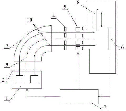
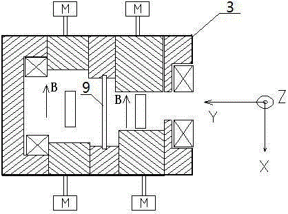
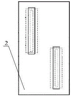
[0027] One, the wide-beam uniformity adjustment device in the ion implanter, which is mainly used in low-temperature polysilicon OLED devices, such as figure 1 As shown, it consists of a multi-filament ion source 1, a multi-slit electrode plate 2, a vertical mass analyzer 3, an analysis light barrier 4, a beam blocking light barrier 5, a fixed Faraday array 6, a uniformity controller 7, a substrate 8, and a conductive plate 9 composition.

[0028] The following takes the wide-beam uniformity adjustment device in the ion implanter used for the production of low-temperature polysilicon OLED devices as an example to introduce the specific adjustment process. The multi-filament ion source 1 generates plasma...


PUM


Abstract

The invention discloses a broad beam uniformity adjusting device of an ion implanter. The broad beam uniformity adjusting device aims to solve the problem that the broad beam uniformity is difficult to control. The broad beam uniformity adjusting device comprises a multi-filament ion source, a multi-slit extraction electrode plate, a vertical mass analyzer, an analysis diaphragm, a beam blocking diaphragm, a substrate and a fixed Faraday array; plasmas are extracted and fed into the vertical mass analyzer by the multi-slit extraction electrode plate and are fed into the analysis diaphragm after being sorted by the vertical mass analyzer, the analysis diaphragm is provided with a plurality of analysis slits, the beam blocking diaphragm is arranged at an outlet of the analysis diaphragm, and broad ion beams are completely fed into a Faraday body of the fixed Faraday array by the aid of the fixed Faraday array; the substrate which horizontally reciprocates is positioned between the beam blocking diaphragm and the fixed Faraday array. The broad beam uniformity adjusting device has the advantages that light paths are simple in structure, broad beam uniformity adjustment operation is simple and convenient, and the broad beam uniformity adjusting device is high in reliability and can be used on low-temperature polycrystalline OLED (organic light emitting diode) device production lines.

Description

technical field [0001] The invention relates to an ion implanter wide-beam uniformity adjustment device, in particular to a wide-beam uniformity adjustment device in an ion implanter for manufacturing low-temperature polysilicon OLED (organic light-emitting diode) devices. Background technique [0002] In the existing high-generation low-temperature polysilicon OLED (organic light-emitting diode) device manufacturing technology, ion implantation technology is used to realize channel implantation in the process, LDD (light drain doped) ion implantation and source / drain implantation, in order to meet low temperature The high precision of the driving circuit of polysilicon, the stability and uniformity of ion implantation become the important key to the success or failure of the device. In order to achieve high uniformity, high standard requirements are put forward for ion implanters, especially beam uniformity, which has become an important indicator for considering ion implan...

Claims


Application Information

Patent Timeline
Patent Type & Authority Patents(China)
IPC IPC(8): H01J37/317H01J37/04H01J37/09
Inventor 王迪平罗宏洋钟新华易文杰
Owner BEIJING SHUOKE ZHONGKEXIN ELECTRONICS EQUIP CO LTD
Why Eureka
Try Eureka