
Electrostatic lens device used for electron acceleration

An electrostatic lens and electron acceleration technology, applied in electron/ion optical devices, parts of particle separator tubes, etc., can solve problems such as influence, and achieve the effect of simple circuit design, good stability, and avoiding the influence of electric field.

Inactive Publication Date: 2014-03-26
DALIAN INST OF CHEM PHYSICS CHINESE ACAD OF SCI
View PDF3 Cites 5 Cited by
  • Summary
  • Abstract
  • Description
  • Claims
  • Application Information

AI Technical Summary

Problems solved by technology

But the front of the repeller is still affected by the electric field

Method used


Image

  • Electrostatic lens device used for electron acceleration

Examples


Embodiment Construction

[0009] The present invention will be described in further detail below in conjunction with the accompanying drawings.

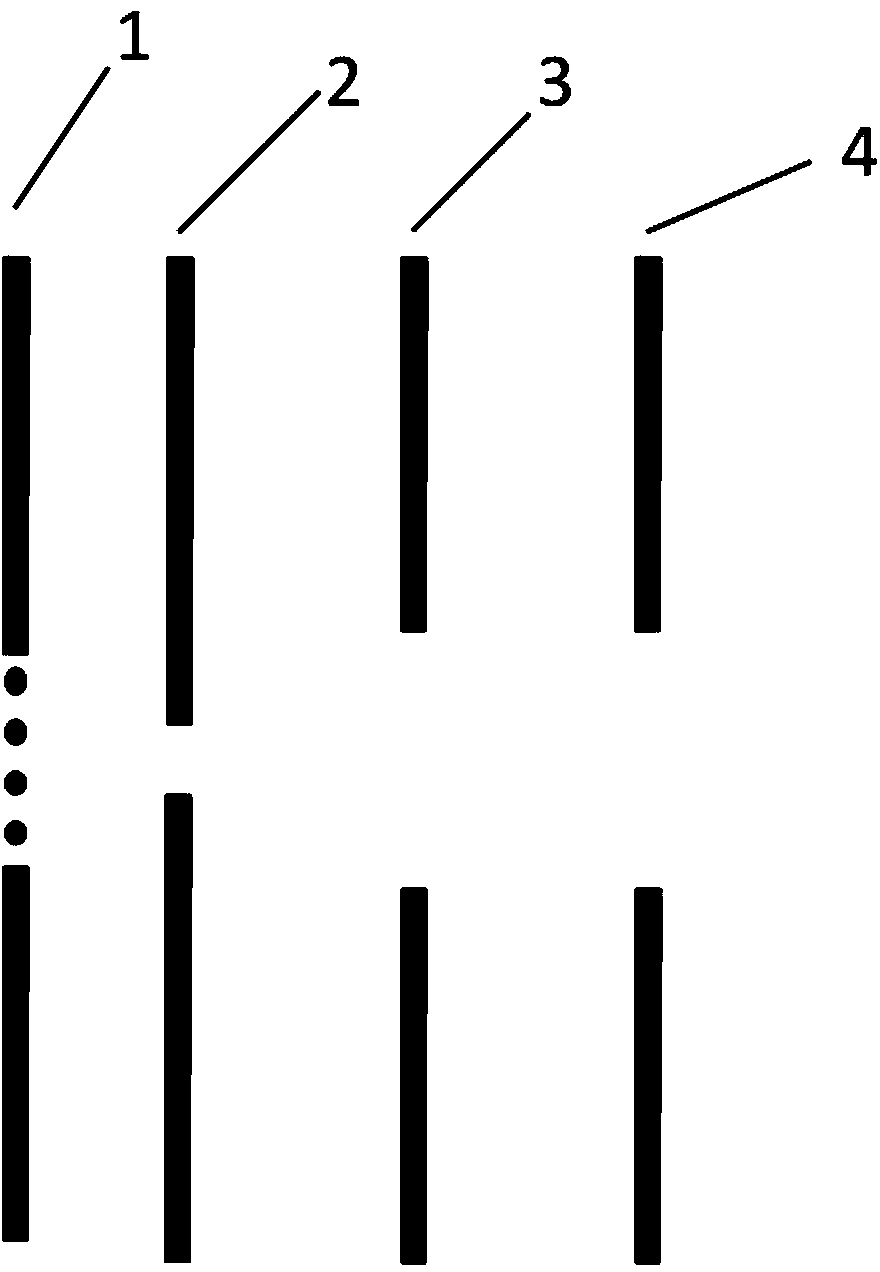
[0010] Such as figure 1 As shown, the present invention provides an electrostatic lens device for electron acceleration, which includes a grid electrode sheet (1), a repelling electrode sheet (2), an accelerating electrode sheet (3) and a ground electrode sheet (4) Wherein, the grid electrode sheet (1) is connected to the repelling electrode sheet (2), the repelling electrode sheet (2) is connected to the accelerating electrode sheet (3), and the accelerating electrode sheet (3) is connected to the grounding electrode sheet (4).

[0011] Add a grid to the first electrode sheet to prevent electrons from being affected by the electric field in front of it. In addition, by adjusting the voltage division ratio between the two electrode sheets of the repelling electrode sheet (2) and the accelerating electrode sheet (3), it can make Imaging energy resolution has ...


PUM


Abstract

An electrostatic lens device used for electron acceleration comprises an electrode plate with an aperture plate, a repelling electrode plate, an accelerating electrode plate and a grounding electrode plate. The device can be used for acceleration of electrons in the desorption process of a photoelectron imaging system. The device is simple in circuit structure design and good in stability and has important effect for distinguishing accelerating and imaging energy of photoelectron imaging electrons.

Description

technical field [0001] The invention belongs to the field of photoelectron imaging, and in particular relates to a device for accelerating electrons in a photoelectron imaging desorption region. Background technique [0002] Imaging technology has a wide range of applications in the field of chemical reaction kinetics, mainly including photolysis fragment ion imaging, reaction product imaging and negative ion photoelectron imaging. In the development of imaging technology, the technology of electrostatic lens has promoted the widespread use of imaging technology. Due to the introduction of "Wiley-McLaren" dual-field acceleration in time-of-flight mass spectrometry to realize the form of spatial focusing, many studies were inspired by this spatial focusing technology and introduced this technology into the research of imaging accelerated electrons. The traditional device uses three electrode sheets, two of which are with grids, which will largely distort the flight trajector...

Claims


Application Information

Patent Timeline
IPC IPC(8): H01J49/06
Inventor 唐紫超谢华刘志凌秦正波张世宇
Owner DALIAN INST OF CHEM PHYSICS CHINESE ACAD OF SCI
Learn More