Uninterruptible power supply input switching control method and device

A control method and technology for controlling equipment, which is applied in the direction of emergency power supply arrangements, electrical components, circuit devices, etc., and can solve problems such as adhesion and relay commonality

Active Publication Date: 2014-03-26
VERTIV CORP
View PDF1 Cites 8 Cited by
  • Summary
  • Abstract
  • Description
  • Claims
  • Application Information

AI Technical Summary

Problems solved by technology

[0006] The embodiment of the present invention provides a control method and equipment for UPS input switching, which is used to solve the common pr

Method used


Image

  • Uninterruptible power supply input switching control method and device
  • Uninterruptible power supply input switching control method and device
  • Uninterruptible power supply input switching control method and device

Examples


Embodiment 1

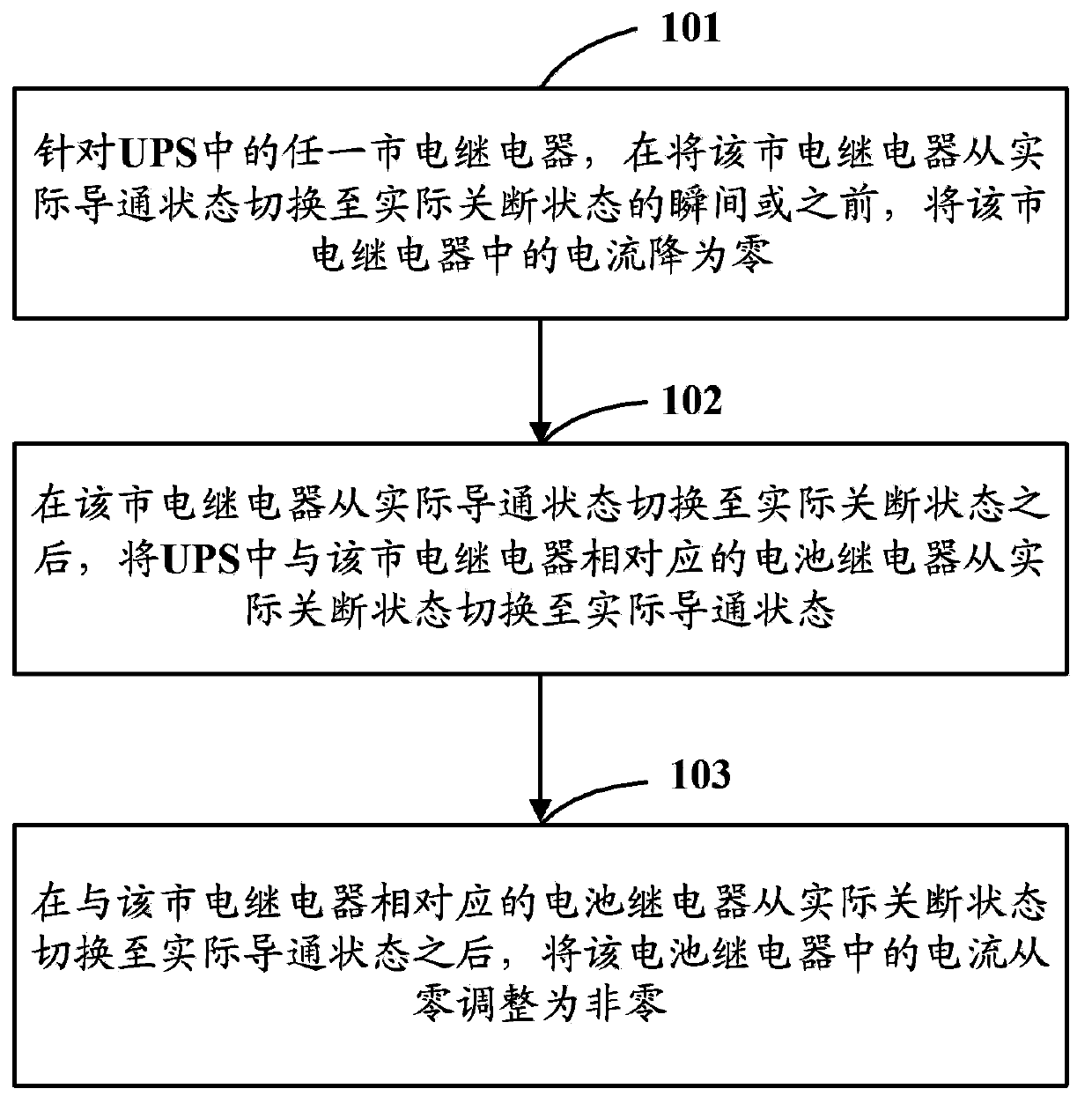
[0030] Embodiment 1 of the present invention provides a control method for UPS input switching. The main principle of the control method is: for any mains relay in the UPS and the battery relay corresponding to the mains relay, at any time, placing at most one of the mains relay and the battery relay corresponding to the mains relay in an actual conduction state, and, for any mains relay or battery relay in the UPS, switching the relay from the actual The current in the relay is reduced to zero at the instant or before the on-state is switched to the actual off-state, and the current in the relay is adjusted from zero after the relay is switched from the actual off-state to the actual on-state is non-zero.

[0031] Further, in UPS, the input switching of UPS can be mainly divided into the following four situations: (1) switching from mains to battery; (2) turning off mains but not switching to battery; (3) switching from battery to mains (4) Turn off the battery, but not swit...

Embodiment 2

[0118] Such as Figure 12 As shown, it is a schematic structural diagram of the control device for UPS input switching in Embodiment 2 of the present invention. The control device includes a first switching module 21 and a second switching module 22, wherein:

[0119] The first switching module 21 is used for any mains relay or battery relay in the UPS, before the moment when the relay is switched from the actual on state to the actual off state, the current in the relay is reduced to zero, or adjust the current in the relay from zero to non-zero after switching the relay from the actual off state to the actual on state.

[0120] Specifically, the first switching module 21 is used to determine the turn-off delay time length of each mains relay and each battery relay in the UPS, and the turn-off delay time length is from the moment when the mains relay or the battery relay performs a turn-off operation to The length of time when it is in the actual off state, and for any mains...


PUM


Abstract

The invention discloses an uninterruptible power supply input switching control method and an uninterruptible power supply input switching control device. The control method includes the following steps that: as for any one commercial power relay or battery relay in an uninterruptible power supply (UPS), at a moment when the relay is switched from an actual switched-on state to an actual switched-off state or before that moment, the current in the relay is reduced to zero; after the relay is switched from the actual switched-off state to the actual switched-on state, the current in the relay is adjusted from zero to nonzero; and, at any moment, one relay at most in any one commercial power relay and a battery relay corresponding to the commercial power relay in the uninterruptible power supply (UPS) is set to the actual switched-on state. With the uninterruptible power supply input switching control method and device provided by the technical schemes of the invention adopted, the problem of concurrent switching on or adhesion of relays caused by the delay and discreteness of the action of the relays when the relays are adopted to realize uninterruptible power supply (UPS) input switching in the prior art can be solved, and therefore, the accuracy and safety of the uninterruptible power supply (UPS) input switching can be improved.

Description

technical field [0001] The present invention relates to the technical field of UPS (Uninterruptible Power System, uninterruptible power supply), in particular to a control method and equipment for UPS input switching. Background technique [0002] UPS is a constant voltage and constant frequency uninterruptible power supply with energy storage device and inverter as the main component. It is mainly used to provide uninterrupted power supply to a single computer, computer network system or other power electronic equipment. When the mains input is normal, the UPS will stabilize the mains and supply it to the load, and charge the internal battery at the same time; when the mains is interrupted (such as an accidental blackout), the UPS will continue to supply 220V AC to the load through the power of the internal battery , to maintain the load in normal working condition and protect the load software and hardware from damage. It can be seen that in UPS, the input switching of ma...

Claims


Application Information

Patent Timeline
IPC IPC(8): H02J9/06
Inventor 田卿张云龙胡小明李业
Owner VERTIV CORP
Why Eureka
Try Eureka