
Isolation type high-power driving circuit and switch power supply using circuit

A drive circuit, isolated drive technology, applied in output power conversion devices, electrical components, conversion equipment that can be converted to DC without intermediate conversion, etc. problems, to achieve the effect of reducing costs and enhancing driving ability

Inactive Publication Date: 2014-03-26
ANHUI DYNAMIC POWER
View PDF4 Cites 5 Cited by
  • Summary
  • Abstract
  • Description
  • Claims
  • Application Information

AI Technical Summary

Problems solved by technology

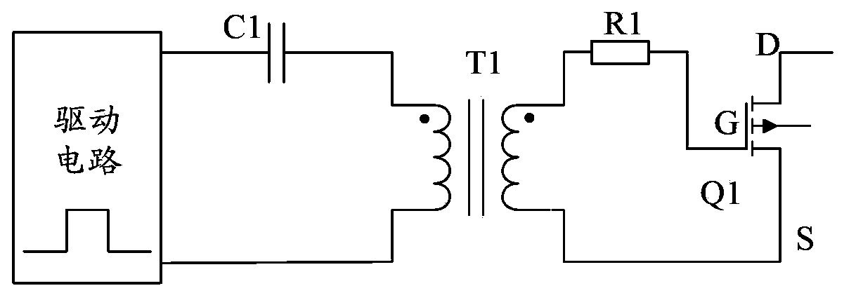
[0003] In the existing traditional power switch tube isolation drive circuit scheme, since the square wave pulse width signal sent by the control circuit passes through the isolation drive transformer T1, the output drive capability is relatively small, so it can only drive a power switch tube with a small power, and The output drive waveform of the isolated driving transformer is greatly distorted; when the duty cycle of the primary side of the driving transformer changes greatly, the positive and negative amplitudes of the output driving pulse width of the secondary side change too much, which may cause the circuit to work abnormally
In addition, when the power switch tube isolation drive circuit works at the maximum output drive capability, the isolation transformer must be designed to be larger in size due to the increase in drive current, which will reduce the power density of the product and increase the cost.

Method used


Image

  • Isolation type high-power driving circuit and switch power supply using circuit
  • Isolation type high-power driving circuit and switch power supply using circuit
  • Isolation type high-power driving circuit and switch power supply using circuit

Examples


Embodiment Construction

[0027] An isolated high-power drive circuit provided by an embodiment of the present invention and a switching power supply using the circuit will be described in detail below with reference to the accompanying drawings.

[0028] like figure 2 As shown, it is a schematic structural diagram of an isolated high-power drive circuit provided by an embodiment of the present invention; the isolated high-power drive circuit includes: an isolated drive transformer, a primary drive circuit, and a secondary drive circuit;

[0029] The primary side drive circuit is used to generate and send a pulse width signal to the isolation drive transformer;

[0030] The isolation drive transformer is used to isolate the pulse width signal to obtain an isolation signal; and transmit the isolation signal to the secondary side drive circuit;

[0031] The secondary side driving circuit is used to enhance the driving capability of the isolated signal and drive the power switch tube.

[0032] Based on...


PUM


Abstract

The invention discloses an isolation type high-power driving circuit and a switch power supply using the circuit. The isolation type high-power driving circuit comprises an isolation driving transformer, a primary side driving circuit and a secondary side driving circuit. The primary side driving circuit is used for generating and sending a pulse width signal to the isolation driving transformer. The isolation driving transformer is used for isolating the pulse width signal and then acquiring an isolation signal and transmitting the isolation signal to the secondary side driving circuit. The secondary side driving circuit is used for driving and amplifying the isolation signal by adopting a driving chip so that a driving signal with driving capacity is acquired to drive a power switch tube. With application of the isolation type high-power driving circuit, the driving capacity can be enhanced and driving of one or multiple parallel-connected high-power switch tubes is facilitated. Therefore, when the power switch tube isolation driving circuit outputs the maximum driving capacity in operation, the isolation driving transformer with smaller size can be selected so that cost of the switch power supply is substantially reduced.

Description

technical field [0001] The invention relates to the technical field of isolated high-power drive circuits, in particular to an isolated high-power drive circuit composed of a drive chip and an isolation drive transformer and a switching power supply using the circuit. Background technique [0002] With the continuous development of power electronics technology, switching power supply has been used more and more. Various circuit topologies in switching power supplies require energy transmission through power devices, which can be driven directly or indirectly. When the power switch tube is applied to a bridge topology or isolation control is required, the power switch tube needs to be driven in isolation. There are many topologies for isolating the drive, such as figure 1 As shown, it is a traditional power switch tube isolation drive circuit, which includes: a primary side drive signal circuit, a primary side DC blocking capacitor C1, an isolation drive transformer T1, a d...

Claims


Application Information

Patent Timeline
Patent Type & Authority Applications(China)
IPC IPC(8): H02M1/08H02M5/10
Inventor 张黎黎
Owner ANHUI DYNAMIC POWER
Learn More