

Magnetic Reactor
A magnetically controlled reactor and reactor technology, applied in the direction of electrical components, output power conversion devices, and conversion equipment that can be converted to DC without intermediate conversion, can solve the problems of increasing equipment cost and manufacturing complexity, and achieve The effect of fast excitation
- Summary
- Abstract
- Description
- Claims
- Application Information
AI Technical Summary
Problems solved by technology
Method used
Image

Examples
Embodiment 1
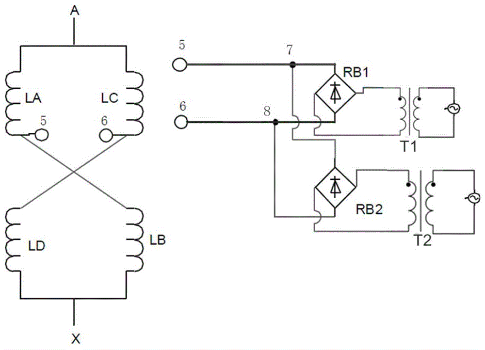
[0021] figure 1 is the circuit schematic diagram of the magnetron reactor provided in this embodiment, such as figure 1 As shown, the magnetron reactor of the present invention includes: a reactor winding and a rectifier bridge circuit, and the output end of the rectifier bridge circuit is directly connected with the coil in the reactor winding to form a loop.
[0022] The reactor winding includes two iron cores, each of which is wound with two sets of coils. One iron core has coils LA and LD, and the other iron core has coils LB and LC. The outgoing end of the coil LA is connected with the incoming end of the coil LB, the outgoing end of the coil LC is connected with the incoming end of the coil LD, and the four sets of coils are in a cross-parallel structure. Each of the iron cores has a set of coils with first taps on them, a first tap 5 is drawn from the outgoing end of the coil LA, a first tap 6 is drawn out from the outgoing end of the coil LC, and the first tap 5 is co...
Embodiment 2
[0038] Figure 4 is the circuit schematic diagram of the magnetron reactor provided in this embodiment, such as Figure 4 As shown, the magnetron reactor of the present invention includes: a reactor winding, a forced shut-off circuit HS and a rectifier bridge circuit. The only difference from the first embodiment is that this embodiment also includes a forced shut-off circuit HS, which is connected between the output end of the rectifier bridge circuit and the coil of the reactor winding, and the forced shut-off circuit HS is used for fast switching. During demagnetization, the current output by the rectifier bridge circuit is disconnected, so that the current passing through the coil is rapidly reduced, and the iron core is rapidly demagnetized.
[0039] Figure 5 is a circuit schematic diagram of a forced shutdown circuit HS provided in this embodiment, such as Figure 5 As shown, the forced shutdown circuit HS includes a controllable device HS1, a controllable device HS2...
Embodiment 3
[0046] Image 6 is the circuit schematic diagram of the magnetron reactor provided in this embodiment, such as Image 6 As shown, the magnetron reactor of the present invention includes: a reactor winding, a forced shut-off circuit HS and a rectifier bridge circuit. The only difference from the second embodiment is that the reactor winding used in this embodiment is a non-fast common reactor winding body, and the specific form of the reactor winding is not limited in the present invention.
[0047] Compared with the second embodiment, the reactor winding of this embodiment also leads out the second tap 1 in the middle of the coil LA, and leads out the second tap 3 in the middle of the coil LD, and there is a controllable connection between the second tap 1 and the second tap 3. The device MS1, leads a second tap 2 in the middle of the coil LC, leads a second tap 4 in the middle of the coil LB, and a controllable device MS2 is connected between the second tap 2 and the second ...
PUM
 Abstract
Description
Claims
Application Information