Advanced peak ballast

A technology of ballast and pinnacle, which is applied in the field of advanced pinnacle ballast, which can solve the problems of increasing copper resistance, unfavorable energy saving, large magnetic loss, etc.

Inactive Publication Date: 2014-03-26
NINGBO AUPUL TELECOMM EQUIP
View PDF5 Cites 0 Cited by
  • Summary
  • Abstract
  • Description
  • Claims
  • Application Information

AI Technical Summary

Problems solved by technology

Please combine figure 2 As shown, when the ballast is in use, the magnetic force lines are better absorbed on both sides of the core column, but the two ends of the core column cannot directly absorb the magnetic force lines and are in a free state, and the magnetic field distribution is uneven, resulting in large magnetic loss
In addition, since the cross-section of the T-shaped stem 11 is rectangular, the circumference of the wire package 12 to be wound is relatively long, which not only increases the cost, but also increases the copper resistance, resulting in greater energy consumption, which is not conducive to energy saving.

Method used


Image

  • Advanced peak ballast
  • Advanced peak ballast
  • Advanced peak ballast

Examples


Embodiment Construction

[0016] The technical solutions of the present invention will be further described below in conjunction with the accompanying drawings and embodiments.

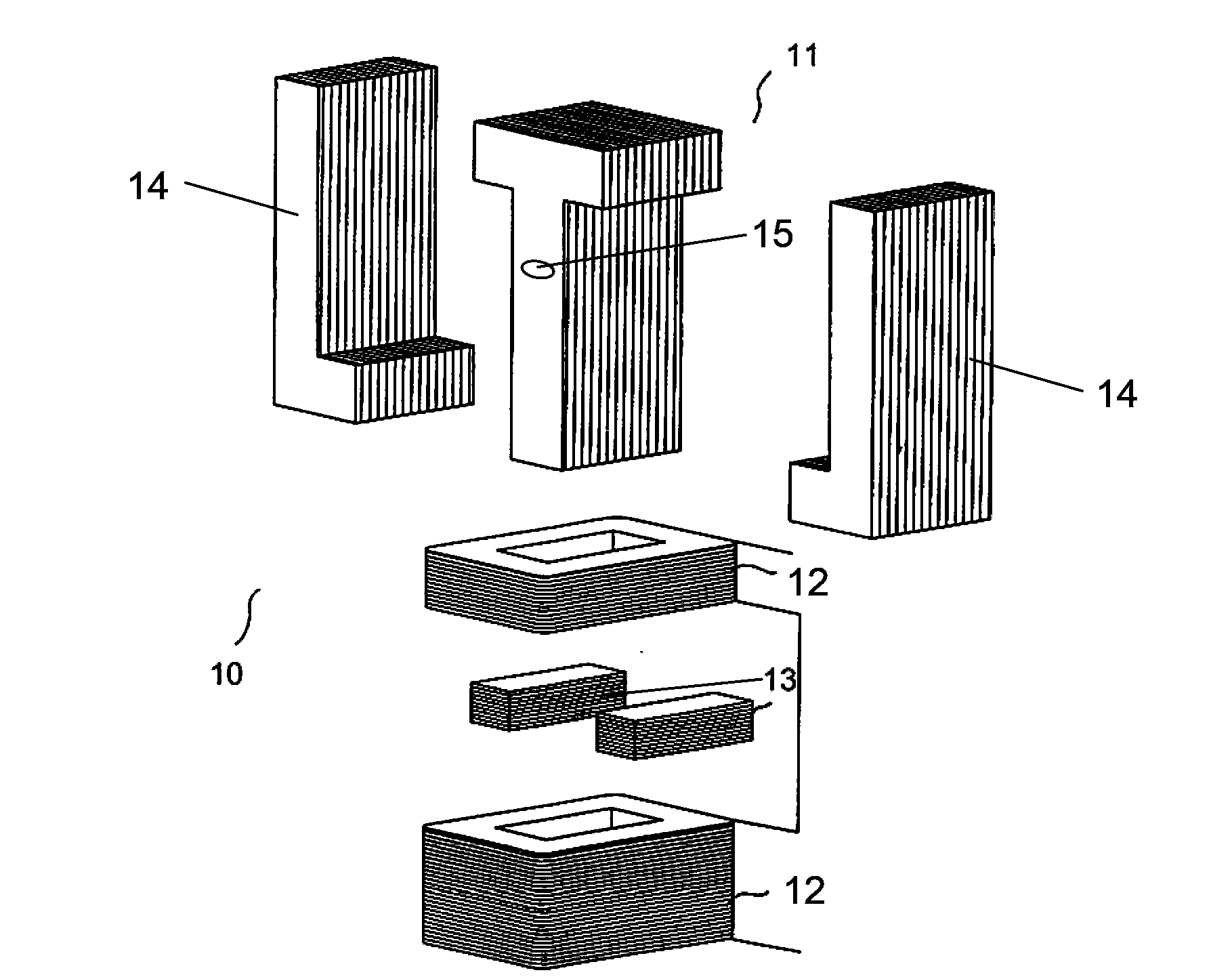
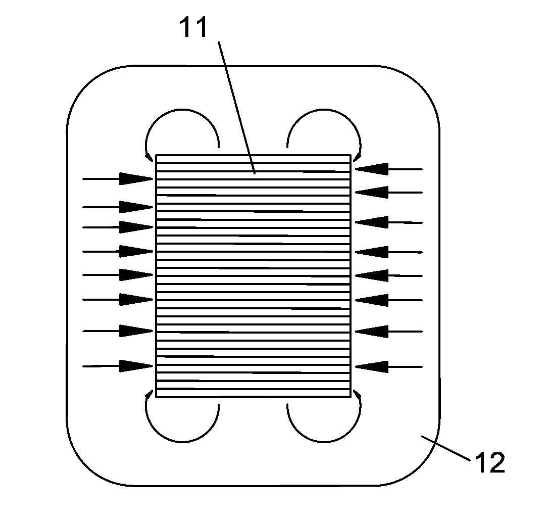
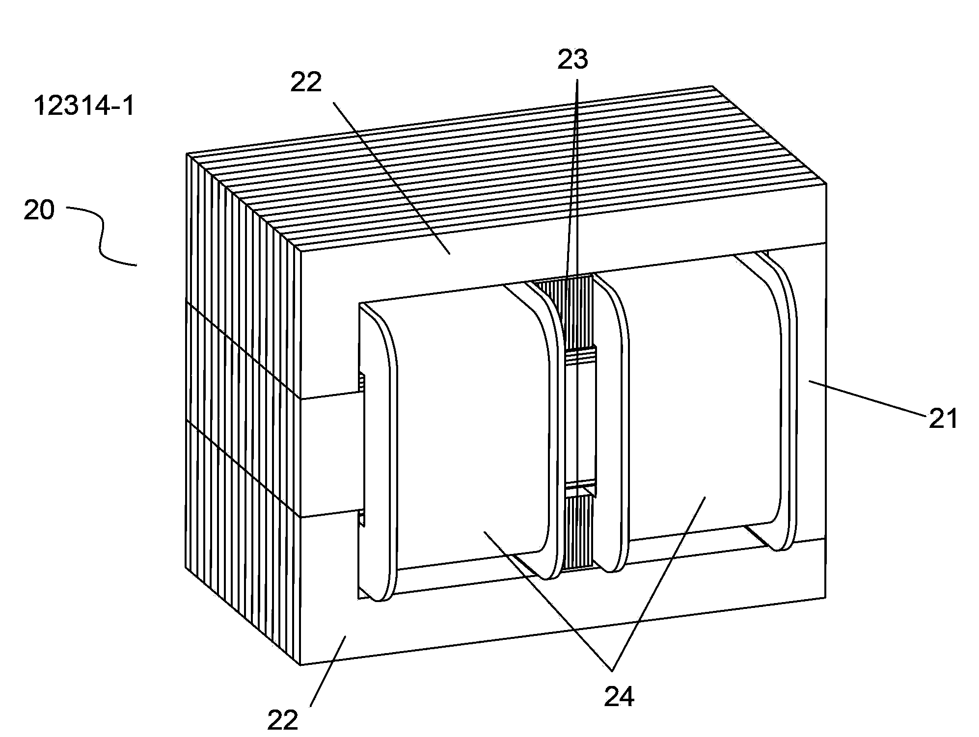
[0017] see image 3 , Figure 4 As shown, the leading peak ballast 20 of the present invention is similar to the prior art, and also includes a core post 21, an L-shaped magnetic yoke 22, an inline magnetic shunt block 23 and a wire package 24. The difference is that the The stem 21 includes a T-shaped main stem 211 with a magnetic flux leakage hole 25 and a trapezoidal auxiliary stem 212 that is separately arranged on both sides of the main stem 211 and integrally formed with it. Two L-shaped yokes 22 are symmetrically arranged on the stem 21. Two magnetic shunt blocks 23 are arranged horizontally in the two spaces formed by the splicing of the core post 21 and the L-shaped yoke 22. Road blocks 23 apart. Wherein, the entire core column 21 is formed by stacking T-shaped silicon steel sheets, and the width of the T-shaped si...


PUM


Abstract

The invention discloses an advanced peak ballast. The advanced peak ballast comprises a core column, L-shaped magnet yokes, beeline-shaped magnetic shunt blocks, and coils, wherein the core column comprises a T-shaped main core column provided with magnetic leakage holes, and a trapezoidal auxiliary core column arranged on two sides of the main core column and integrated with the main core column; two L-shaped magnet yokes are symmetrically arranged on two sides of the core column, and are jointed with the core column; the two magnetic shunt blocks are respectively transversely arranged in two spaces formed by jointing the core column and the L-shaped magnet yokes; two coils are wound on the main core column and the auxiliary core column, and are separated by the magnetic shunt blocks. The ballast provided by the invention can improve the magnetic line adsorption surface on two ends of the core column through the trapezoidal auxiliary core column, thereby realizing more uniform magnetic line distribution nearby, reducing magnetic line liberation, improving electromagnetic conversion efficiency and effectively reducing magnetic loss. Additionally, the overall cross section of the core column is similar to round shape, so that the perimeter of the winded coils can be reduced, thereby reducing cost, reducing copper resistance, lowering energy loss and saving energy.

Description

technical field [0001] This invention relates to ballasts, and more particularly, to a leading peak ballast. Background technique [0002] The structure of the traditional leading peak ballast 10 is as follows figure 1 As shown, it includes T-shaped core post 11, L-shaped magnetic yoke 14, inline magnetic shunt block 13 and wire package 12, T-shaped core post 11 has flux leakage holes 15, and two L-shaped magnetic yokes 14 are arranged symmetrically. On both sides of the core column and spliced ​​with it, the two magnetic shunt blocks 13 are respectively arranged horizontally in the two spaces formed by splicing the T-shaped core column 11 and the L-shaped magnetic yoke 14, and the wire packages 12 are placed on the core column respectively, and are connected by Magnetic shunt blocks 13 are separated. In addition, the T-shaped core column 11, the L-shaped magnetic yoke 14, and the inline magnetic shunt block 13 are all formed by stacking silicon steel sheets of correspondi...

Claims


Application Information

Patent Timeline
Patent Type & Authority Applications(China)
IPC IPC(8): H05B41/02
Inventor 周尧达张乃铫
Owner NINGBO AUPUL TELECOMM EQUIP
Why Eureka
Try Eureka