Camshaft with an axially displaceable cam pack

A technology of camshafts and cam groups, applied in the direction of elements with teeth, cams, belts/chains/gears, etc., can solve the problems of expensive design and expensive production

Active Publication Date: 2014-03-26
THYSSENKRUPP PRESTA TECCENTER AG
View PDF9 Cites 5 Cited by
  • Summary
  • Abstract
  • Description
  • Claims
  • Application Information

AI Technical Summary

Problems solved by technology

Disadvantageously, the use of the support tube for mounting the cam and the adjustment element results in an expensive design, and the cam must be arranged on the support tube with the necessary connectio

Method used


Image

  • Camshaft with an axially displaceable cam pack
  • Camshaft with an axially displaceable cam pack
  • Camshaft with an axially displaceable cam pack

Examples


Embodiment Construction

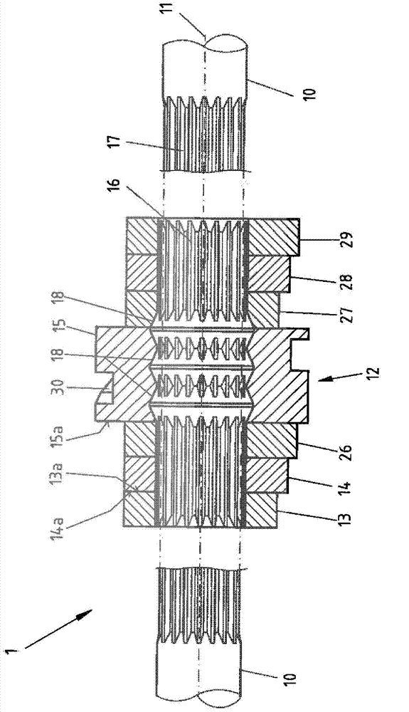
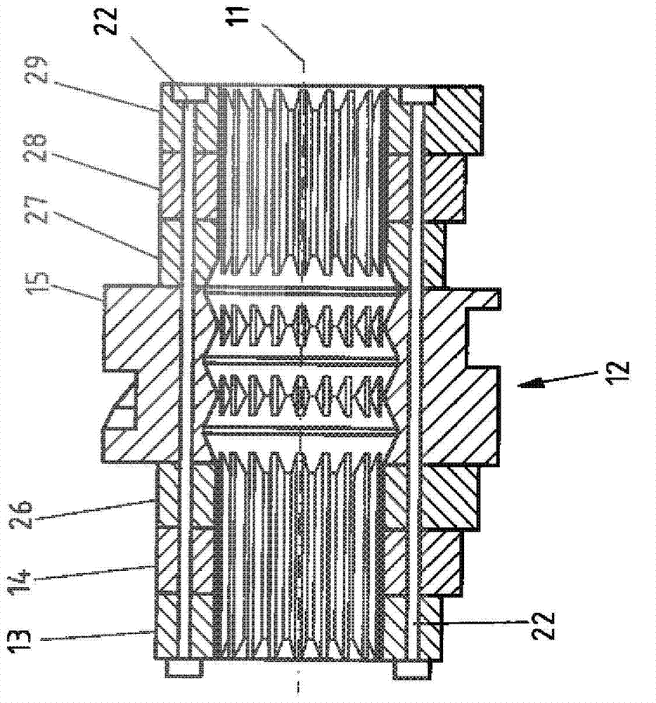
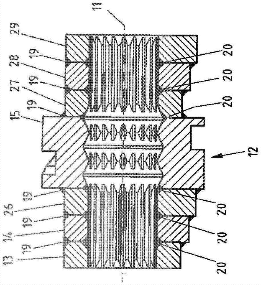
[0075] figure 1 An exemplary embodiment of a camshaft 1 with a cam set 12 is shown, which is embodied with the features of the invention. The camshaft 1 comprises a carrier shaft 10 which is shown interrupted in the seating area of ​​a cam set 12 . The carrier shaft 10 can be mounted to rotate about an axis 11 , for example in a cylinder head of an internal combustion engine.

[0076] The cam set 12 comprises, for example, six cams 13 , 14 , 26 , 27 , 28 and 29 , in which the adjustment element 15 is provided and into which guide grooves 30 are introduced at the outer periphery of the adjustment element 15 . Cams 13 , 14 and 26 are located on a first side of adjustment element 15 and cams 27 , 28 and 29 are located on a second, opposite side of adjustment element 15 . Through holes extend through the cams 13 , 14 , 26 , 27 , 28 , 29 and through the adjustment element 15 , through which the carrier shaft 10 passes. Inserted into this through-bore formed by the individual com...


PUM


Abstract

The invention relates to a camshaft (1) and a method for producing a camshaft (1) having a support shaft (10) which is rotatably mounted in a shaft axis (11), at least one cam pack (12) being axially displaceably mounted on the support shaft (10), and the cam pack (12) comprising at least two cams (13, 14, 26, 27, 28, 29, 32, 33, 34) and at least one adjusting element (15) for axially adjusting the cam pack (12). According to the invention, the cams (13, 14, 26, 27, 28, 29, 32, 33, 34) and the at least one adjusting element (15) are interconnected axially adjacent to each other and can be accommodated directly on the support shaft (10) as a combined entity by means of a rolling body guide with rolling bodies (31) such that the combined entity can be axially displaced.

Description

technical field [0001] The invention relates to a camshaft with a carrier shaft rotatably mounted about an axis, wherein at least one cam group is arranged axially movably on the carrier shaft, and wherein the cam group comprises at least two cams and at least one for cam Set of adjusting elements for axial adjustment. [0002] Such camshafts are used in internal combustion engines, which can be operated with adjustable valve lift or adjustable valve timing. The valves of the internal combustion engine are controlled by a cam set, and the cam set is axially movably arranged on the shaft of the rotating support frame. The valves can be actuated with different cams by axial displacement of the cam set on the carrier shaft, wherein the different cams can have different cam shapes. The cam lobes can be substantially geometrically pronounced, or the positions of the cam lobes can vary relative to each other in a circumferential direction. Cams are also known as zero-lift cams. ...

Claims


Application Information

Patent Timeline
IPC IPC(8): F01L1/047F16H53/02B21D53/84
CPCF16H25/08F16H53/025B22D19/00F01L1/047F01L1/34F01L2013/0052F01L2001/0473F16H25/10B21D53/845Y10T74/2102Y10T74/2101Y10T29/49293
Inventor T·宾得尔P·威斯纳
Owner THYSSENKRUPP PRESTA TECCENTER AG
Why Eureka
Try Eureka