Torque transmission device with electrical insulation
What is AI technical title?
AI technical title is built by Patsnap AI team. It summarizes the technical point description of the patent document.
A technology of torque transmission device and insulating element, applied in the direction of transmission device, fluid transmission device, transmission device parts, etc., can solve the problems of increased duration, difficult assembly of torsional shock absorbers, etc., and achieve the effect of increasing the structure space
Active Publication Date: 2013-05-08
ZF FRIEDRICHSHAFEN AG
View PDF8 Cites 4 Cited by
Summary
Abstract
Description
Claims
Application Information
AI Technical Summary
This helps you quickly interpret patents by identifying the three key elements:
Problems solved by technology
Method used
Benefits of technology
Problems solved by technology
Furthermore, it has been found that the installation of the plastic element in the spring box makes the assembly of the torsional vibration damper difficult and significantly increases the costs due to the additional duration
Method used
Image
Click on the blue label to locate the original text in one second.
Reading with bidirectional positioning of images and text.
Examples
Embodiment Construction
[0051] Similar or similarly acting elements are identified below with the same reference numerals.
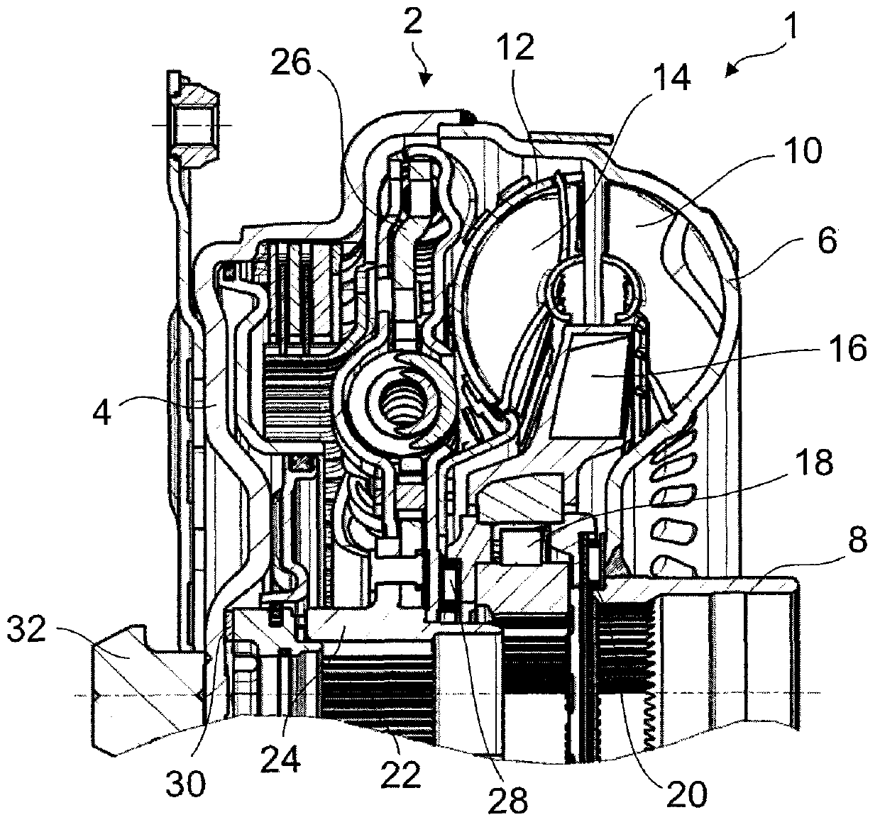
[0052] figure 1 A wet-running clutch assembly 1 in the form of a hydraulic torque converter is shown. On its side facing the drive (not shown), the housing 2 has a housing cover 4 which is fixedly connected to the impeller housing 6 . The impeller housing 6 merges into the impeller hub 8 in the radially inner region.
[0053] The impeller casing 6 together with the impeller blades forms a pump impeller 10 which cooperates with a turbine 14 having a turbine casing 12 with turbine blades and a stator 16 with stator blades. The pump wheel 10 , the turbine wheel 14 and the guide wheel 16 form a hydraulic circuit in a known manner.
[0054] The guide wheel 16 is arranged on a freewheel 18 which is supported axially on the pump hub 8 via an axial bearing 20 . The pump hub 8 is hollow and therefore accommodates the transmission input shaft 22 in its interior.
[0055] The transmi...
PUM
Abstract
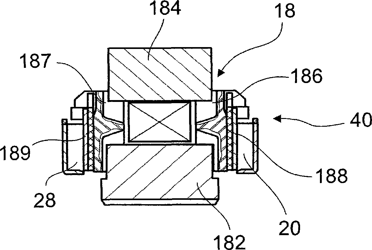
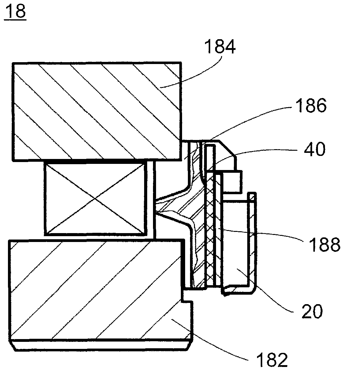
A torque transmission device, particularly for a motor vehicle, for the transmission of a torque from a driving unit, particularly from an internal combustion engine, to a driven unit, particularly a transmission, has at least one bearing (18,20,28,30,35,504,508,604,610,704,708,804,808)location which has at least one bearing support acting in axial and / or radial direction, wherein an insulation element(40) preventing a flow of electric current is provided in the region of the at least one bearing (18,20,28,30,35,504,508,604,610,704,708,804,808)location.
Description
technical field [0001] The invention relates to a torque transmission device, in particular for a motor vehicle, to transmit torque from a drive unit, in particular from an internal combustion engine, to an output unit, in particular to a transmission with at least one bearing support frame (Lagerstelle), the bearing support The carrier has bearings acting in at least one axial and / or radial direction. Background technique [0002] This type of torque transmitting device may be, for example, a clutch pack, a twin inertia flywheel, or a torque converter. This type of torque transmitting device is usually arranged in the powertrain of a vehicle between a drive unit (engine) and an output unit (transmission). However, it has been shown in modern powertrains that during starting of the vehicle via the starter, although the main part of the current can, as usual, be directed to the body via the ground wire, the remaining current intensity can be obtained from the starter Engine...
Claims
Application Information
Patent Timeline
Application Date:The date an application was filed.
Publication Date:The date a patent or application was officially published.
First Publication Date:The earliest publication date of a patent with the same application number.
Issue Date:Publication date of the patent grant document.
PCT Entry Date:The Entry date of PCT National Phase.
Estimated Expiry Date:The statutory expiry date of a patent right according to the Patent Law, and it is the longest term of protection that the patent right can achieve without the termination of the patent right due to other reasons(Term extension factor has been taken into account ).
Invalid Date:Actual expiry date is based on effective date or publication date of legal transaction data of invalid patent.

