Sandwich composite component and production process therefor

a composite component and composite technology, applied in the field of sandwich components, can solve problems such as deformation zones and surface defects, and achieve the effect of reducing the proportion of fibres in the outer layer

Active Publication Date: 2017-05-30
DAIMLER AG
View PDF11 Cites 3 Cited by
  • Summary
  • Abstract
  • Description
  • Claims
  • Application Information

AI Technical Summary

Benefits of technology

[0011]The foam layer can consist of a foamed thermoplastic plastic, for example in order to promote the connection to the fibre-reinforced thermoplastic outer layer. Cost-efficient polyolefins, such as polypropylene and polyethylene, are suggested for use. The use of thermoplastic plastics has the advantage that a fusing and melting of the foam with the outer layer can occur. This is, in particular, of significance in the region of the edges. Preferably, a melting of the outer layers and foam layer or the thermoplastic proportions thereof is carried out in the edge regions of the sandwich component, such that a sealing of the edges is achieved. This is, for example, achieved by an increased pressing force in the hot press in the edge region. For the use in the visible region, it is herein advantageous to press the edge connection directly at the component contour. Hereby, on the one hand, a component trimming is generated, and on the other hand an almost blunt joining of the outer layers is enabled, whereby a qualitatively high-value component trimming is enabled. Hereby, a high-value trimming is enabled. Therein, a sandwich component is formed, in which the edges are sealed or are closed outwardly by melting the outer layer and foam layer. As the outer layer and the foam layer consist of thermoplastic polymers, a polymer mixture is at least partially formed by the melting.
[0014]The sealing of the edges is particularly advantageous as moisture entering the paper honeycomb core is hereby prevented and a higher mechanical load is implemented during edge impact.
[0017]In order to improve the bond between the honeycomb core layer and the fibre-reinforced thermoplastic outer layer, the sandwich component can have an additional thermoplastic intermediate layer between the honeycomb core layer and the outer layer. It can be favourable if the physical-chemical properties such as the melting or glass transition temperature of the thermoplastics of the outer layer are similar or correspond to one another.
[0020]The production method enables the cost-efficient in-situ lamination of the sandwich component by the use of a foam layer in order to prevent the imprinting of surface defects on the decorative layer.
[0023]Due to the at least partial melting of the thermoplastic plastic matrix, a good bond is achieved between honeycomb core and outer layer in that the end edges of the honeycomb webs are received by the thermoplastic matrix material of the outer layer.
[0026]A good bond between honeycomb core and outer layer is also hereby achieved by the at least partial melting of the thermoplastic plastic matrix, wherein, here, the end edges of the honeycomb webs are now received by the thermoplastic matrix material of the intermediate layer, which provides the connection between honeycomb core and outer layer and at the same time prevents the penetration of fibre material into the honeycomb hollow spaces and thus the reduction of the fibre proportion in the outer layer.

Problems solved by technology

In the use of honeycomb cores having thermoplastic outer layers, it can, however, as a consequence of the flowability of the thermoplastic required between the layers for the production of the bond, lead to surface defects, in particular in the deformation zones, such as for example the imprinting of the honeycomb structure.

Method used


Image

  • Sandwich composite component and production process therefor
  • Sandwich composite component and production process therefor
  • Sandwich composite component and production process therefor

Examples


Embodiment Construction

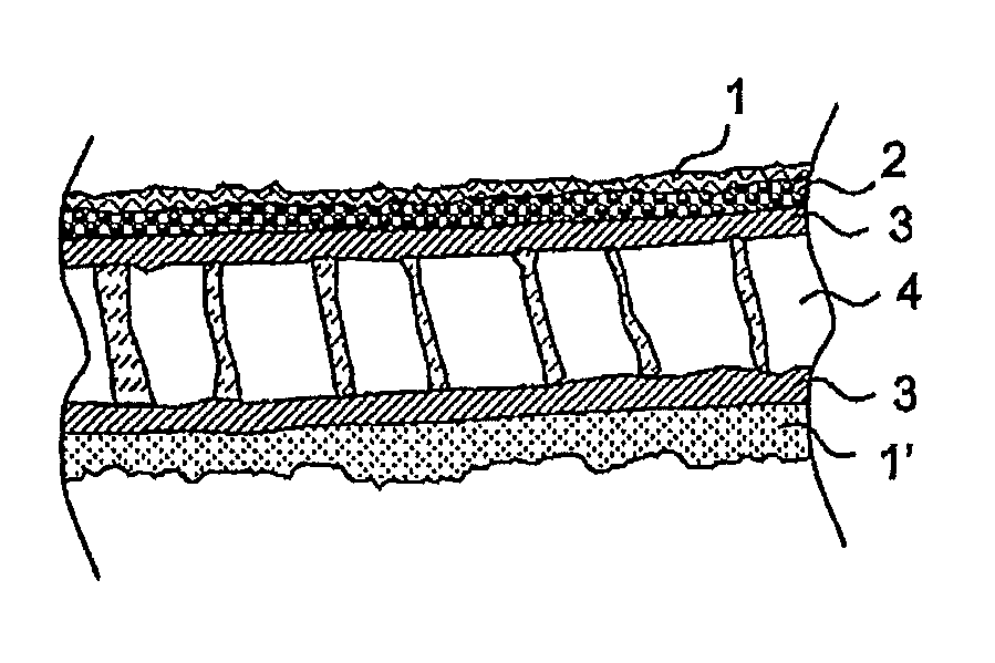
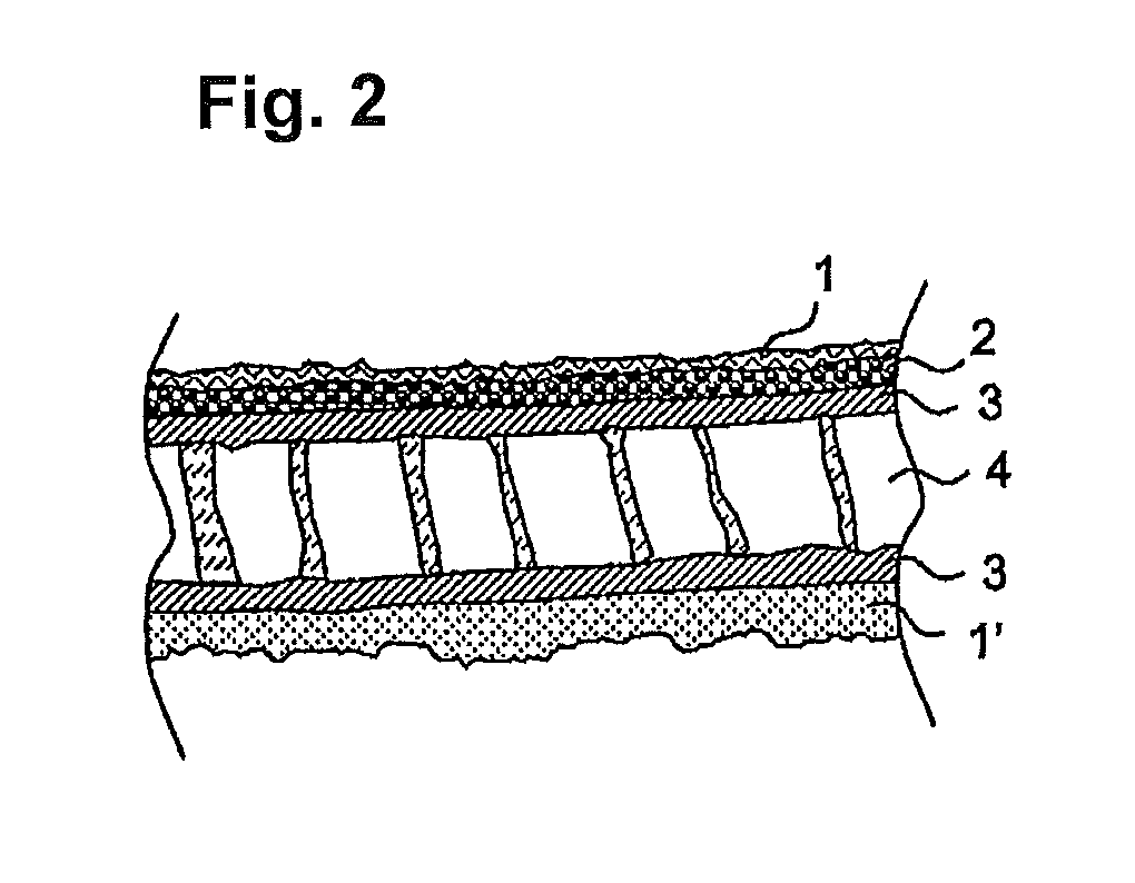
[0034]A sandwich component according to the invention comprises at least one decorative layer on the visible side of the component as well as the honeycomb core and the fibre-reinforced thermoplastic outer layers, wherein, by the use of a foam layer as an intermediate layer between the decorative layer (which can be, for example, textile goods) and the sandwich outer layer, this can serve for the lamination of surface defects.

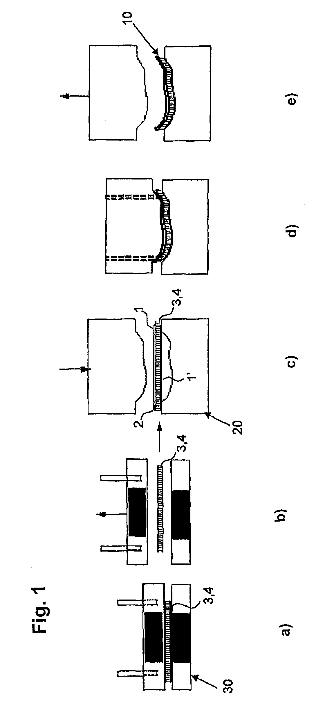
[0035]An in-situ lamination in the moulding pressing tool 20 has been proved as a cost-efficient production process. The production of the sandwich component 10 is depicted schematically in FIG. 1.

[0036]In step a), a multi-layer arrangement made from fibre-reinforced thermoplastics 3 for the formation of the outer layers and the honeycomb core layer 4 arranged therebetween is heated in a heating tool 30, e.g. a hot press. Organic sheets or hybrid textiles made from reinforcement and matrix fibres are, for example, considered as fibre-reinforced thermoplastic la...


PUM

PropertyMeasurementUnit
densityaaaaaaaaaa
thicknessaaaaaaaaaa
thicknessaaaaaaaaaa

Abstract

A sandwich component (10) having a honeycomb core layer (4) and at least one fiber-reinforced thermoplastic outer layer (3) and the corresponding production method. The outer layer (3) is connected to the honeycomb core layer (4) by a thermoplastic material. At least one side of the sandwich component (10 has a decorative layer (1,1′), which is arranged on the outer layer (3). The sandwich component (10) furthermore has at least one foam layer (2), which is arranged between the outer layer (3) and the decorative layer (1,1′), and which is connected to the outer layer (3) and the decorative layer (1,1′).

Description

BACKGROUND OF THE INVENTION[0001]Field of the Invention[0002]The invention relates to a sandwich component having a honeycomb core and outer layers, as well as a production method for the same.[0003]Description of the Related Art[0004]In the course of the lightweight construction strategy in the construction of motor vehicles to reduce both the fuel consumption and carbon dioxide emissions, components having a sandwich structure are increasingly used, which can provide a clearly reduced weight compared to conventional components due to the low density of the material which forms the core, and sufficient strength values due to a suitable selection of outer layer material. Further advantages of such sandwich structures lie in their thermal and acoustic properties.[0005]A sandwich component made from cost-efficient materials having improved mechanical properties and / or improved surface quality is known from DE 10 2010 005 456 A1. The sandwich component described there comprises a honey...

Claims


Application Information

Patent Timeline
Patent Type & Authority Patents(United States)
IPC IPC(8): B32B3/12B32B37/14B29C70/08B32B27/10B29C70/46B32B27/06B29C43/20B29C43/52B32B3/04B32B37/04B29K1/00B29K23/00B29K101/12B29K105/00B29K105/04B29K105/06B29K309/08B29L31/30B29L31/60
CPCB32B3/12B29C43/206B29C43/52B29C70/086B29C70/088B29C70/465B32B3/04B32B27/065B32B27/10B32B37/146B29K2001/00B29K2023/12B29K2101/12B29K2105/045B29K2105/06B29K2105/253B29K2309/08B29L2031/30B29L2031/608B32B37/04B32B2250/05B32B2250/24B32B2305/022Y10T428/236
Inventor STAMP, BENNOBLUMENSTOCK, TOBIASWITTIG, ROMAN
Owner DAIMLER AG
Why Eureka
Try Eureka