
Work fixture for cutting groove at axle housing midpiece

A technology of tooling fixtures and axle housings, applied in the field of tooling fixtures, can solve problems such as rough interfaces, inconvenient production, and low efficiency of milling machine cutting grooves, and achieve the effect of stable positioning

Active Publication Date: 2014-04-02
GUANGDONG FUWA HEAVY IND
View PDF6 Cites 5 Cited by
  • Summary
  • Abstract
  • Description
  • Claims
  • Application Information

AI Technical Summary

Problems solved by technology

[0002] The axle housing is welded by two halves of the middle section of the axle housing. The interface of the middle section of the forged axle housing is relatively rough. It is necessary to cut the interface into a bevel to form a V-shaped bevel. Nowadays, milling machines are generally used for processing, but the efficiency of milling machine cutting grooves is low. It takes 20 minutes for the middle section of each axle housing, which brings inconvenience to subsequent production. Therefore, it is necessary to find a suitable bevel cutting method. Using plasma cutting, it only takes 2 minutes to cut a bevel in the middle section of the axle housing, which greatly improves the work efficiency. efficiency, but because the middle section of the axle housing is arc-shaped, its positioning is difficult, and it is necessary to design a fixture suitable for the shape of the middle section of the axle housing, with stable and accurate positioning

Method used


Image

  • Work fixture for cutting groove at axle housing midpiece
  • Work fixture for cutting groove at axle housing midpiece
  • Work fixture for cutting groove at axle housing midpiece

Examples


Embodiment Construction

[0027] The preferred embodiments of the present invention will be described below in conjunction with the accompanying drawings. It should be understood that the preferred embodiments described here are only used to illustrate and explain the present invention, and are not intended to limit the present invention.

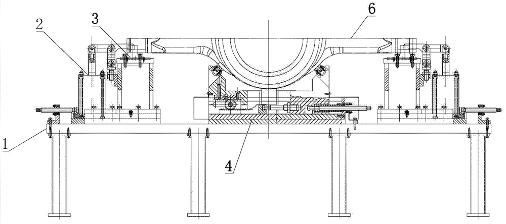
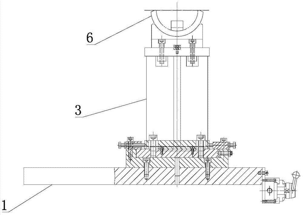
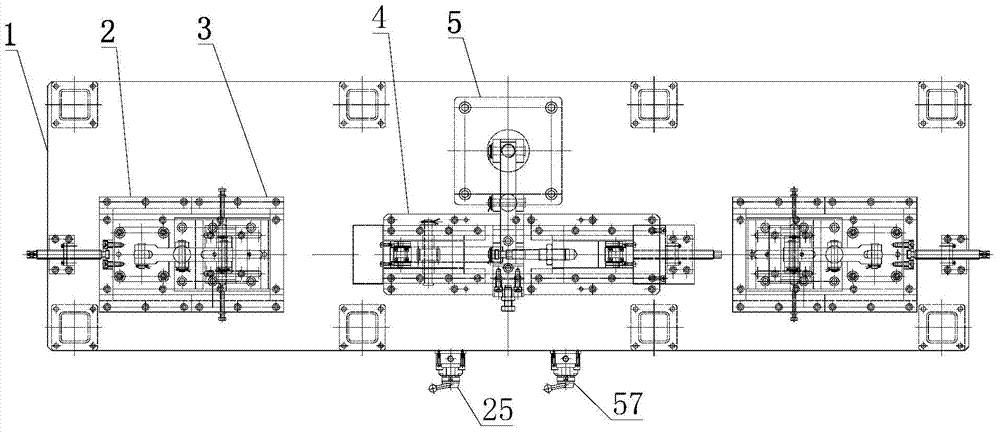
[0028] Such as Figure 1 to Figure 7 As shown, the tooling fixture for cutting and beveling the middle section of the axle housing according to the present invention includes a platform 1, an end shaft support structure 3 arranged on both sides of the platform, an end shaft clamping mechanism 2 for clamping the two ends of the middle section 6 of the axle housing, The middle supporting structure 4 arranged between the two end shaft supporting structures 3 and the middle clamping mechanism 5 for clamping the middle part of the middle section 6 of the axle housing.

[0029] The end shaft support structure 3 includes a slide rail 31 arranged on the platform 1, a slide ...


PUM


Abstract

The invention discloses a work fixture for cutting a groove at an axle housing midpiece. The work fixture comprises a platform, a supporting structure and a clamping structure, wherein the supporting structure comprises end shaft supporting structures arranged at the two sides of the platform and a middle supporting structure arranged between the end shaft supporting structures, each end shaft supporting structure comprises a pedestal, a cushion block support arranged on the pedestal and a cushion block arranged on the cushion block support, the end face of each cushion block is provided with an arc-shaped inner groove, the middle supporting structure comprises a base, and a first supporting block and a second supporting block arranged at the left and right sides, the base is provided with a self-centering positioning mechanism for ensuring the synchronous movement of the first supporting block and the second supporting block, and the clamping structure comprises end shaft clamping mechanisms arranged at the two ends of an axle housing and used for clamping the two ends of the axle housing and a middle clamping mechanism for clamping the middle part of the axle housing. Through supporting and clamping the two ends and the middle of the axle housing midpiece for positioning, the positioning is accurate, the clamping is firm, the adjusting is convenient, and clamping and positioning for axle housing midpieces of different specifications and models can be realized.

Description

technical field [0001] The invention belongs to the technical field of tooling fixtures, and in particular relates to a tooling fixture for cutting and beveling the middle section of an axle housing. Background technique [0002] The axle housing is welded by two halves of the middle section of the axle housing. The interface of the middle section of the forged axle housing is relatively rough. The interface needs to be cut into a bevel to form a V-shaped bevel. Now it is generally processed by a milling machine, but the milling machine is inefficient in cutting grooves. It takes 20 minutes for the middle section of each axle housing, which brings inconvenience to subsequent production. Therefore, it is necessary to find a suitable bevel cutting method. Using plasma cutting, it only takes 2 minutes to cut a bevel in the middle section of the axle housing, which greatly improves the work efficiency. efficiency, but because the middle section of the axle housing is arc-shaped,...

Claims


Application Information

Patent Timeline
Patent Type & Authority Applications(China)
IPC IPC(8): B23K37/04B23K10/00
CPCB23K37/0435B23K37/0461
Inventor 吴志强赵常斌林禹尚徐力山
Owner GUANGDONG FUWA HEAVY IND
Learn More