Plane fixture and method for machining box fault isolator

A technology for processing boxes and fixtures, used in manufacturing tools, metal processing equipment, metal processing machinery parts, etc., can solve the problems of destroying the processing positioning position, affecting the processing accuracy, and high labor intensity, achieving simple production and replacement, adaptability Wide range of capabilities, the effect of simplifying the clamping process

Inactive Publication Date: 2014-04-02
CHONGQING WANGJIANG IND
View PDF6 Cites 4 Cited by
  • Summary
  • Abstract
  • Description
  • Claims
  • Application Information

AI Technical Summary

Problems solved by technology

[0009] (1) When planing and processing the partition gap, it is necessary to correct the box, determine the starting position of the partition gap of the box, record the angle degree on the dividing head for milling, and then gradually change the indexing angle according to the process requirements, and process until the fracture There is no clear prompt for the end position of the notch. The operator needs to record and calculate the angle position of the dividing head for milling before the end of processing. If the calculation is wrong, the box will be scrapped.
[0010] (2) Every time a box is replaced, the original processing positioning position will be destroyed. When the next box needs to be processed, it must be repositioned and corrected. The operation is cumbersome and labor-intensive
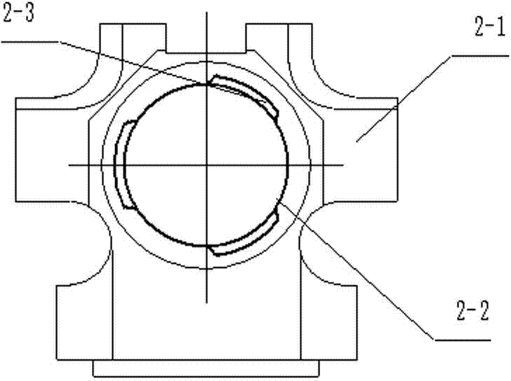
[0011] (3) Due to the gap of 2-3 in the box body, such as figure 2 There are three shown. The box needs to be rotated 360 degrees during processing. Since the box is clamped and positioned by the combination of V-shaped blocks and spacers, it is necessary to re-press the box every time the processing part is changed, and the adjustment frequency is high. , labor-intensive, multiple clamping is prone to positioning errors, affecting machining accuracy
[0012] (4) Multiple clamping and calibration are required for each processing of a box partition, and the processing efficiency is low

Method used


Image

  • Plane fixture and method for machining box fault isolator
  • Plane fixture and method for machining box fault isolator
  • Plane fixture and method for machining box fault isolator

Examples


Embodiment Construction

[0055] The present invention will be described in further detail below in conjunction with the accompanying drawings and specific embodiments.

[0056] see Figure 4 , Figure 5 , Figure 6 , Figure 7 , Figure 8 and Figure 9 As shown, the planing jig for box partition processing of the present invention includes a jig bottom plate 4-1: a part is installed on the right end of the jig bottom plate 4-1, and the other part is installed on the right side of the indexing mechanism 8 and is connected with the installation The positioning clamping mechanism 6 corresponding to a part on the right end of the clamp base plate 4-1, the indexing mechanism 8 installed on the left end of the clamp base plate 4-1, the positioning clamping mechanism 6 and the indexing mechanism 8 and the transmission mechanism 7 installed on the clamp bottom plate 4-1, and the profiling mechanism 9 located outside the left side of the indexing mechanism 8;

[0057] From Figure 4 and Figure 6 It ca...


PUM


Abstract

The invention discloses a plane fixture and method for machining a box fault isolator. The plane fixture comprises a fixture bottom plate (4-1), a positioning and clamping mechanism (6), an indexing mechanism (8), a transmission mechanism (7) and a profiling mechanism (9), one portion of the positioning and clamping mechanism (6) is mounted at the right end of the fixture bottom plate (4-1), the other portion of the positioning and clamping mechanism (6) is mounted on the right side of the indexing mechanism (8) and corresponds to the portion mounted at the right end of the fixture bottom plate (4-1), the indexing mechanism (8) is mounted at the left end of the fixture bottom plate (4-1), the transmission mechanism (7) is positioned between the positioning and clamping mechanism (6) and the indexing mechanism (8) and mounted on the fixture bottom plate (4-1), and the profiling mechanism (9) is positioned outside the left side of the indexing mechanism (8). The method includes the steps: turning box fault isolation rings on a horizontal lathe; planing box fault isolation notches in a planer by the aid of the plane fixture. The plane fixture and method for machining the box fault isolator have the advantages that positioning is accurate, and quality is ensured.

Description

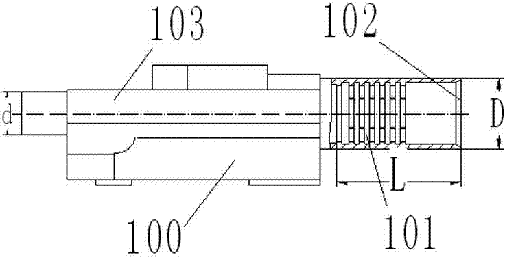
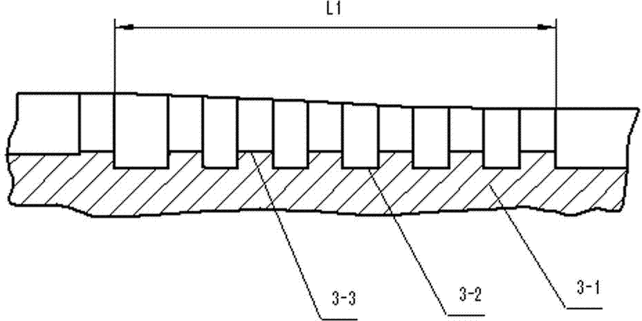
technical field [0001] The invention relates to mechanical processing, in particular to a planer fixture and method for processing box partitions. Background technique [0002] There is a kind of box in some special mechanical equipment, see figure 1 , figure 2 and image 3 As shown, the box has a box partition 101, a small end 103, a large end 102, a box body 2-1, a partition ring 2-2, three partition gaps 2-3, and a partition part 3-1 1. Section 3-2 of the processed part of the partition notch, and 3-3 of the section of the non-processed notch part of the partition ring. There are multiple partition rings 2 - 2 arranged in the box body 100 at intervals from each other. The distance L between the box partition 101 and the end surface of the big end 102 is 265 mm, and each box partition 101 is helically distributed on the inner circumference of the box body 100 at a helix angle. Therefore, the general milling method is difficult to process and guarantee the quality. ...

Claims


Application Information

Patent Timeline
Patent Type & Authority Applications(China)
IPC IPC(8): B23Q3/06B23Q16/02B23Q35/00
CPCB23Q3/062B23Q16/065B23Q35/04
Inventor 王波廖书惠陈晓江张琳英
Owner CHONGQING WANGJIANG IND
Why Eureka
Try Eureka