Die-cutter

A die-cutting machine and frame technology, applied in metal processing, etc., can solve the problems of excessive waste, unfavorable production and processing, and increased production costs, so as to reduce labor intensity, improve precision and quality, and increase feeding speed Effect

Inactive Publication Date: 2014-04-02
SUZHOU DONGFU ELECTRONICS
View PDF6 Cites 6 Cited by
  • Summary
  • Abstract
  • Description
  • Claims
  • Application Information

AI Technical Summary

Problems solved by technology

[0002] Before the general die-cutting machine processes the material, there is no certain regulation on the size of the material, so it is easy to cause waste of material during processing. At the same time, when processing the material, it often does not control the material, so that The machine is processed according to the set distance. This design is easy to produce too much waste for production, which is not conducive to production and processing, and increases production costs.

Method used


Image

  • Die-cutter
  • Die-cutter
  • Die-cutter

Examples


Embodiment Construction

[0013] The present invention is described below in conjunction with accompanying drawing.

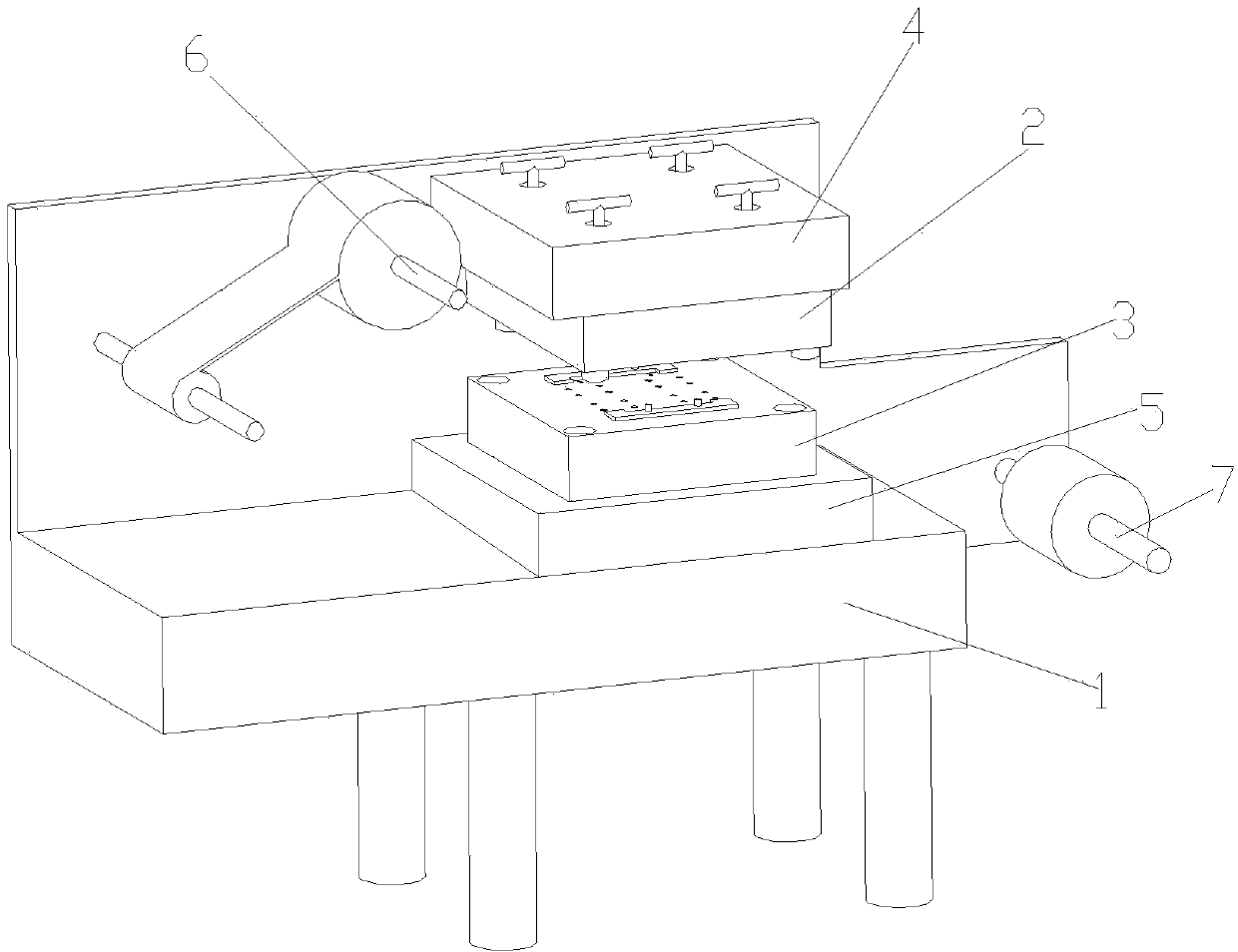
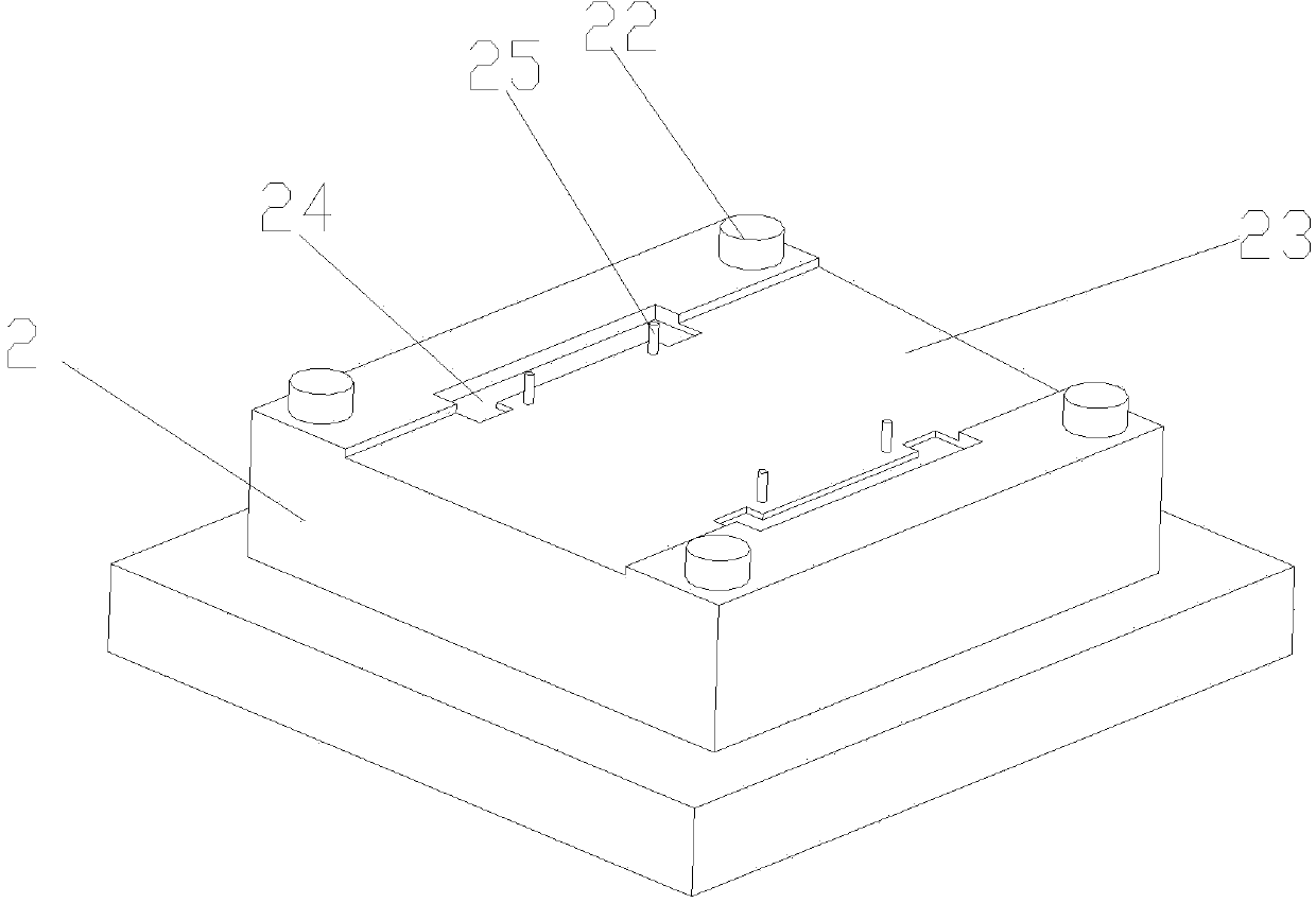
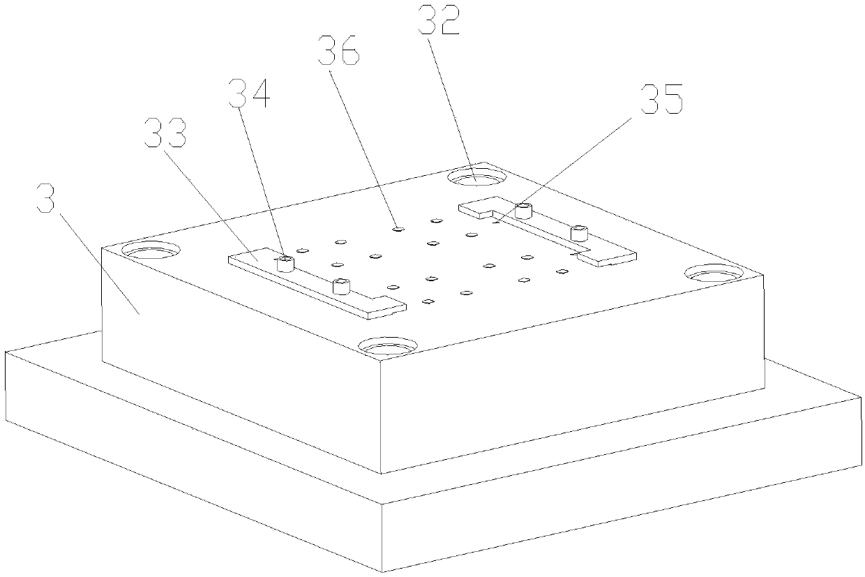
[0014] attached Figure 1-3 Be a kind of die-cutting machine described in the present invention, comprise frame 1, mould, upper fixed plate 4, lower fixed plate 5, feeding device 6 and receiving device 7; Described upper and lower fixed plate 4,5 are installed on On the frame 1; the feeding device 6 and the receiving device 7 are respectively arranged on the front and rear sides of the frame 1; the mold includes an upper mold 2 and a lower mold 3; the upper mold 2 is fixed on the upper fixed plate 4; The lower mold 3 is fixed on the lower fixing plate 5; the four corners of the upper mold 2 are provided with positioning columns 22; the middle part of the upper mold 2 is a concave step 23; the two sides of the concave step 23 are also provided with clamping grooves 24; the upper mold 2 inside the clamp groove 24 is provided with a positioning thimble 25; the four corners of the lower mo...


PUM


Abstract

The invention discloses a die-cutter comprising a rack, dies, an upper fixing plate, a lower fixing plate, a feeding device and a receiving device. The upper fixing plate and the lower fixing plate are mounted on the rack, the feeding device and the receiving device are arranged on the front side and the rear side of the rack respectively, the dies include an upper die and a lower die which are fixed on the upper fixing plate and the lower fixing plate respectively, positioning posts are arranged at four corners of the upper die, a downwards-concave step is arranged in the middle of the upper die, clamping plate grooves are further formed on two sides of the downwards-concave step, positioning ejection pins are arranged on the upper die on the inner sides of the clamping plate grooves, positioning grooves matched with the positioning posts on the upper die are formed at four corners of the lower die, two clamping plates matched with the clamping plate grooves are arranged on the lower die and fixed through adjusting bolts, positioning holes matched with the positioning ejection pins are formed on opposite inner sides of the two clamping plates, and gaps are formed between the opposite inner sides of the two clamping plates and the lower die. By the design of the die-cutter, labor intensity of operators is reduced, feeding speed is increased, and production cost is lowered.

Description

technical field [0001] The invention relates to a die-cutting machine, which belongs to the technical field of material processing machinery. Background technique [0002] Before the general die-cutting machine processes the material, there is no certain regulation on the size of the material, so it is easy to cause waste of material during processing. At the same time, when processing the material, it often does not control the material, so that The machine is processed according to the set distance. Such a design is easy to generate too much waste for production, which is not conducive to production and processing, and increases production costs. Contents of the invention [0003] In view of the above-mentioned technical problems, the object of the present invention is to propose a die-cutting machine with accurate positioning and stable material travel. [0004] The technical solution of the present invention is realized like this: a kind of die-cutting machine compris...

Claims


Application Information

Patent Timeline
Patent Type & Authority Applications(China)
IPC IPC(8): B26F1/38B26F1/44B26D7/01B26D7/18
Inventor 杜宏举
Owner SUZHOU DONGFU ELECTRONICS
Why Eureka
Try Eureka