Full-electric plastic injection molding machine

An all-electric, injection machine technology, applied in the field of plastic injection molding, can solve the problems of high manufacturing cost and complex structure of the all-electric plastic injection machine, and achieve the effect of compact structure, large economic potential and low cost

Active Publication Date: 2014-04-02
李健
View PDF6 Cites 5 Cited by
  • Summary
  • Abstract
  • Description
  • Claims
  • Application Information

AI Technical Summary

Problems solved by technology

As a result, it will inevitably lead to two servo-driven all-electric plastic injection machines with complex structures and high manufacturing costs

Method used


Image

  • Full-electric plastic injection molding machine
  • Full-electric plastic injection molding machine
  • Full-electric plastic injection molding machine

Examples


Embodiment 1

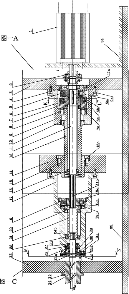
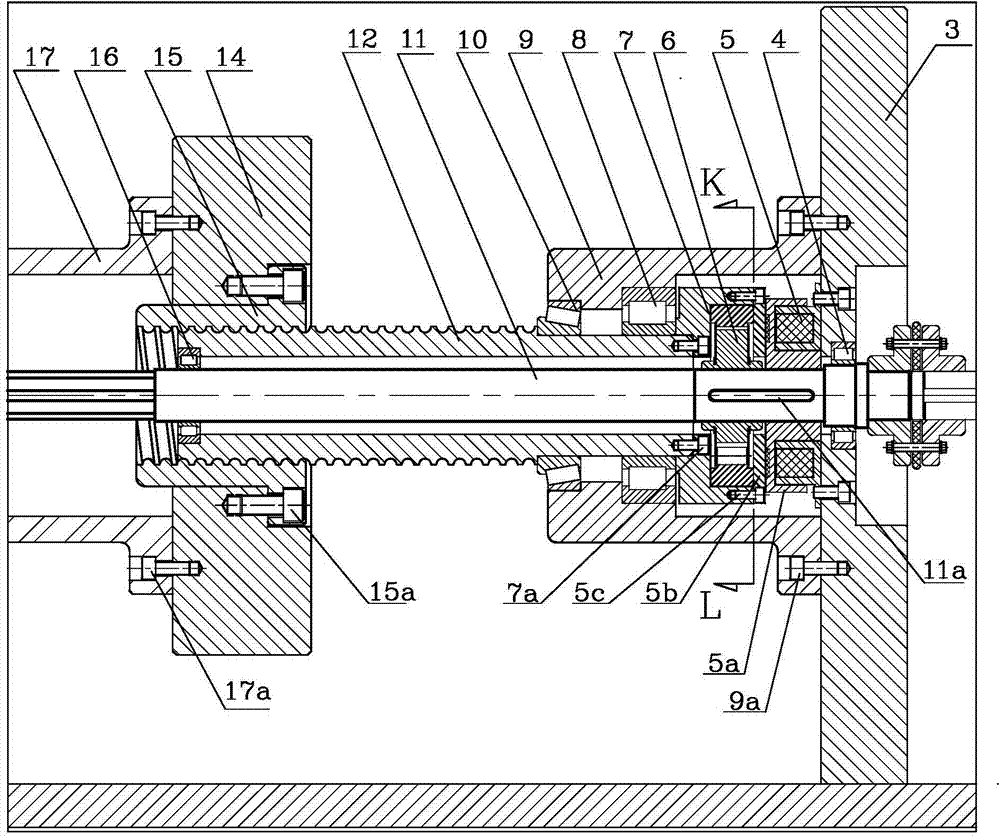
[0041] Example 1: Please refer to the attached figure 1 , which shows a single ball screw cylinder type all-electric plastic injection machine, which includes a single-servo motor injection mechanism and an electric mold clamping mechanism, wherein the single-servo motor injection mechanism includes a servo motor 1, a spindle 11 driven by the servo motor 1, Ball screw barrel, two clutches, injection pusher, ball nut, drive and injection screw. The servo motor drives the main shaft 11 to rotate through the coupling 2, and the main shaft 11 is fixed by two bearings, one is the roller bearing 4 fastened in the center of the end plate 3, and the other is the roller fixed at the end of the ball screw cylinder 12 bearing 16.

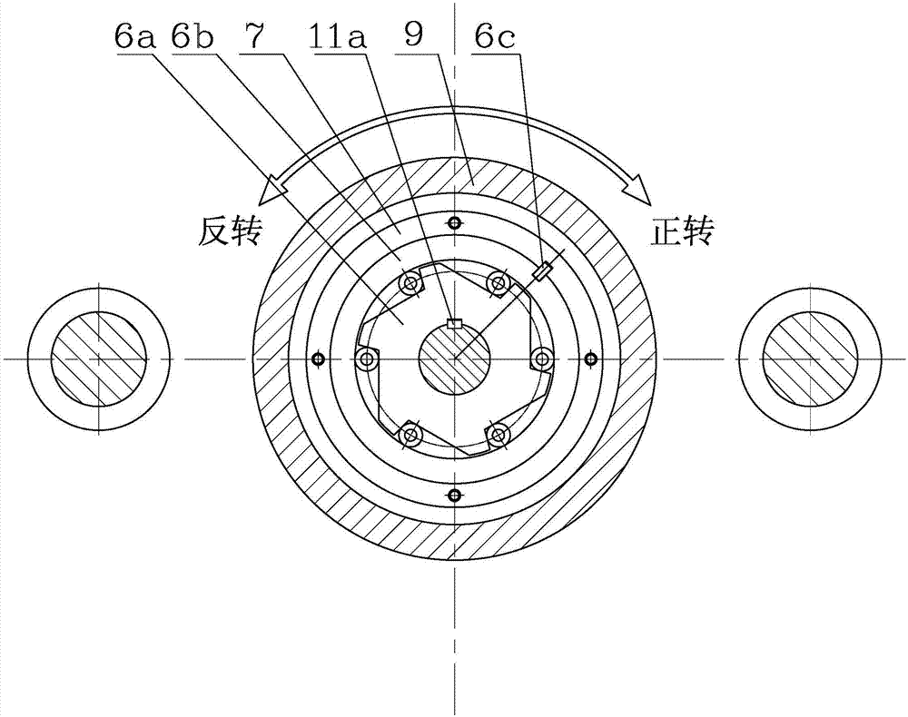
[0042] Please refer to the attached figure 2 There are two clutches on the tail of the main shaft, a mobile electromagnetic clutch 5 and a one-way overrunning clutch 6. The mobile electromagnetic clutch 5 includes an electromagnet, an armature 5a and a driv...

Embodiment 2

[0052] Example 2: Please refer to the attached Figure 5-8 , In this embodiment, a double ball screw cylinder structure is adopted, which also includes a servo motor 36 , a main shaft 38 and two ball screw cylinders 50 . The servo motor 36 is fastened on the motor support plate 39 and is linearly connected with the main shaft 38 through a coupling 37 . Main shaft 38 is fixed with roller bearing 40 and roller bearing 53 . Two of the ball screw cylinders 50 are arranged parallel to the main shaft and driven by the main shaft.

[0053] Two clutches are arranged on the main shaft, one is a moving electromagnetic clutch 42 and the other is a one-way overrunning clutch 43. The electromagnet of mobile electromagnetic clutch is fixed on the bottom of clutch assembly cover 41 with screw 42b, and armature 42a is connected with main shaft 38 with key 38a. Key 38a and armature 42a are a sliding fit. The key 38a rotates with the armature 42a, while the armature 42a can slide linearly. ...


PUM


Abstract

The invention provides a full-electric plastic injection molding machine, comprising a single-servo motor injection molding mechanism and an electric die locking mechanism, wherein the single-servo motor injection molding mechanism comprises a servo motor, a main shaft driven by the servo motor, a ball screw barrel, two clutches, an injection molding push plate, a ball nut, a driving piece and an injection molding screw; a one-way overrunning clutch on the main shaft drives the ball screw barrel to rotate during the forward rotation of the servo motor; when the servo motor is in backward rotation and under the state that the mobile electromagnetic clutch is electrified, the ball screw barrel is drive to rotate reversely; the injection molding push plate moves as the ball nut rotates and the ball nut is engaged with the ball screw barrel; the driving piece is arranged on the injection molding push plate; the driving piece is connected with the injection molding screw; the driving piece is matched with the main shaft through a screw electromagnetic clutch. The full-electric plastic injection molding machine is capable of realizing a plurality of complex actions such as feeding and injection molding of the injection molding mechanism by virtue of the servo motor and the front and rear clutches. The mold locking mechanism perfectly completes the whole injection molding process by employing the innovated full-electric crank-link mechanism. Furthermore, the full-electric plastic injection molding machine is ingenious in structure, and economic and practicable.

Description

【Technical field】 [0001] The invention relates to the technical field of plastic injection molding, in particular to an all-electric servo-driven plastic injection machine. 【Background technique】 [0002] Since the 1990s, all-electric plastic injection machines have been available. After more than 20 years of development, it has become more and more perfect. With its energy saving, precision, high speed and low noise, it is very popular among users. Hydraulic injection machines will inevitably be phased out gradually. However, the current all-electric plastic injection machine has a complex structure and is expensive, so it cannot completely replace the cheap hydraulic injection machine. The main reason is that in the current all-electric plastic injection machine, two servo motors are required for the two actions of injection and feeding to perform the injection action and the rotary feeding of the screw respectively. The action of screw feeding is closely related to th...

Claims


Application Information

Patent Timeline
Patent Type & Authority Applications(China)
IPC IPC(8): B29C45/03B29C45/46B29C45/64B29C45/76
CPCB29C45/03B29C45/64B29C45/76B29C2045/1792B29C2045/5024B29C2945/76498B29C2945/76665
Inventor 李光辉李健
Owner 李健
Why Eureka
Try Eureka