Interlocking brake equipment of saddle form vehicle

A saddle-riding vehicle and braking device technology, applied to bicycle brakes, bicycle accessories, etc., can solve the problems of rising assembly man-hours, increasing the number of parts, and difficult ratios, and achieve the effect of suppressing the impact

Active Publication Date: 2014-04-02
HONDA MOTOR CO LTD
View PDF7 Cites 22 Cited by
  • Summary
  • Abstract
  • Description
  • Claims
  • Application Information

AI Technical Summary

Problems solved by technology

[0005] On the other hand, in a saddle-riding vehicle, it is difficult to easily secure the ratio due to space constraints around the brake pedal.
[0006] In addition, in the int

Method used


Image

  • Interlocking brake equipment of saddle form vehicle
  • Interlocking brake equipment of saddle form vehicle
  • Interlocking brake equipment of saddle form vehicle

Examples


no. 1 Embodiment approach )

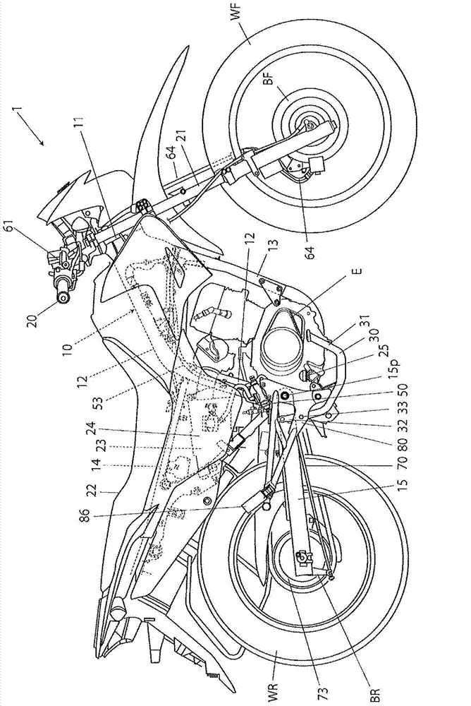
[0067] figure 1 It is a side view showing an example of a motorcycle as a saddle-riding vehicle to which the first embodiment of the interlocking brake device for a saddle-riding vehicle according to the present invention is applied. This motorcycle 1 has a vehicle frame 10 . The vehicle frame 10 has: a head pipe 11; a main frame 12 extending rearward from the head pipe 11 and then extending downward; a down pipe 13 extending downward from the head pipe 11 and then extending backward, and A lower portion of the main frame 12 is combined; and a rear frame 14 extending rearward from the main frame 12 .

[0068] The handle 20 and the front fork 21 are rotatably supported by the head pipe 11 , and the front wheel WF is pivotally supported by the lower end of the front fork 21 . By turning the handle 20, the front wheels WF can be steered.

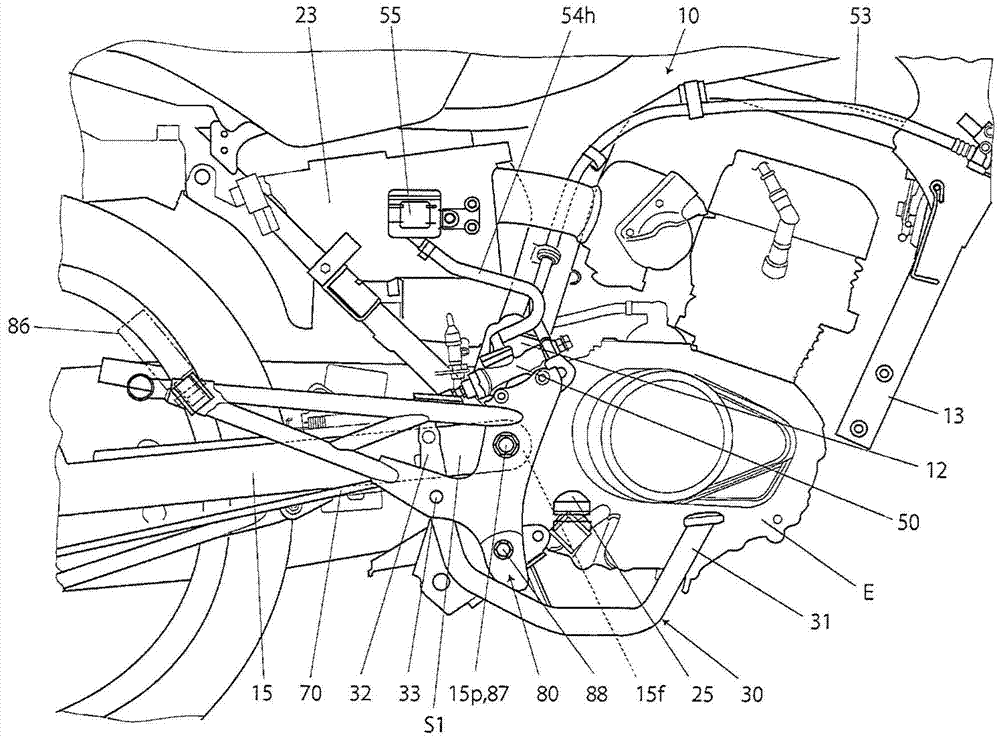
[0069] The front end portion 15f of the swing arm 15 ( image 3 ) is vertically supported by a swing arm pivot 15 p at the lower rear port...

no. 2 Embodiment approach )

[0131] Figure 8 It is a side view showing an example of a motorcycle as a saddle-riding vehicle to which the second embodiment of the interlocking brake device for a saddle-riding vehicle according to the present invention is applied.

[0132] This motorcycle includes: a main frame 213 extending downward and rearward from a head pipe 212 that supports a handle 216 so as to be operable; a rear frame 217 extending upward and rearward from a rear end portion 213r of the main frame 213; The vehicle frame (vehicle body) 10 has a pivot frame 214 extending downward from a rear end portion 213 r of the main frame 213 .

[0133] The front fork 211 is steerably supported by the head pipe 212 via the handle 216 , and the front wheel WF is pivotally supported on the lower end of the front fork 211 . The front end portion 15f of the swing arm 15 is vertically swingably supported by the pivot frame 214 via the swing arm pivot 15p, and the rear wheel WR is pivotally supported by the rear e...


PUM


Abstract

The present invention relates to an interlocking brake equipment of a saddle form vehicle, which can properly ensure the rate of a transmitting power forced or transmitting distance of an equalizer relative to an operating force or distance of a brake pedal. The interlocking brake equipment of the saddle form vehicle includes the brake pedal (30), a pedal arm (31) that forward extends with relative to a pedal pivot (33), and a transmitting arm (32) that together rotates with the pedal arm (31) and upward extends relative to the pedal pivot (33). The interlocking brake equipment of the saddle form vehicle also includes the equalizer (40) that is connected with the transmitting arm (32) of the brake pedal (30). One end of the equalizer is connected with a rear transmitting unit (70) that transmits operating power to a rear-wheel brake (BR), the other end of the equalizer is connected with a main hydraulic cylinder (50) that receives the operating power from a front wheel brake (BF). During the observation of side-looking, a swing arm (15p) is provided in such a location: the front of the location is surrounded by a power unit (E), and the rear of the location is surrounded by the transmitting arm (32), the upward side of the location is surrounded by the main hydraulic cylinder (50) and the below side of the location is surrounded by pedal arm (31).

Description

technical field [0001] The invention relates to a linkage braking device for a saddle-riding vehicle. Background technique [0002] Conventionally, as an interlocking brake device for a saddle-riding vehicle, for example, as shown in Patent Document 1 (particularly FIG. 18 ), such an interlocking brake device is known: when the brake pedal 7 is operated, 2 , through the brake lever 62 to the mechanical rear wheel brake B R3 impart braking force, and, will be equalized by 12 2 The distributed operating force passes through the main hydraulic cylinder 68 and the linked brake transmission system 4 4 To the brake lever 6 2 Side guidance, thus also for hydraulic front wheel brakes B F2 Give braking force. [0003] Patent Document 1: Japanese Patent Application Laid-Open No. 09-058434 [0004] In the above-mentioned interlocking brake device for a saddle-riding vehicle, the operating force of the brake pedal is distributed by the equalizer into a force for pulling the rear b...

Claims


Application Information

Patent Timeline
IPC IPC(8): B62L3/08B62L3/04
Inventor 中村广则谷一彦若林威家田义久西川丰武藤健二细田和作
Owner HONDA MOTOR CO LTD
Why Eureka
Try Eureka