Sludge drying device and method

A sludge drying and sludge technology, applied in the direction of sludge treatment through temperature control, dehydration/drying/concentrated sludge treatment, etc., can solve the problems of waste of useful sludge resources, environmental pollution, etc., to improve heat exchange efficiency, The effect of prolonging the residence time and enhancing the heat transfer effect

Active Publication Date: 2014-04-02
ELECTRIC POWER RES INST OF GUANGDONG POWER GRID +1
View PDF7 Cites 5 Cited by
  • Summary
  • Abstract
  • Description
  • Claims
  • Application Information

AI Technical Summary

Problems solved by technology

In addition, if a large amount of untreated sludge is randomly stacked and discharged, it will

Method used


Image

  • Sludge drying device and method
  • Sludge drying device and method
  • Sludge drying device and method

Examples


Example Embodiment

[0034] Example 1

[0035] A sludge drying device includes a housing, an intermediate sleeve, a central shaft and a driving mechanism; the central shaft is sleeved in the intermediate sleeve, and the outer wall of the central shaft and the inner wall of the intermediate sleeve form a first cavity. Both ends of the first cavity are respectively provided with a first inlet and a first outlet; the intermediate sleeve is sleeved in the housing, the outer wall of the intermediate sleeve and the inner wall of the housing form a second cavity, and both ends of the housing are respectively provided with a first Two inlets and a second outlet; the outer wall of the central shaft is provided with a spiral-shaped first partition along the axial direction of the central axis, and the outer wall of the intermediate sleeve is provided with a spiral-shaped second partition along the axial direction of the intermediate sleeve; The driving mechanism drives the intermediate sleeve to rotate along i...

Example Embodiment

[0040] Example 2

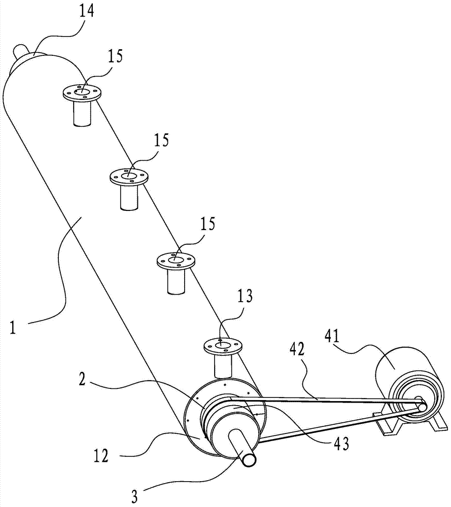
[0041] A sludge drying device, such as figure 1 As shown, it includes a housing 1, an intermediate sleeve 2, a central shaft 3 and a driving mechanism.

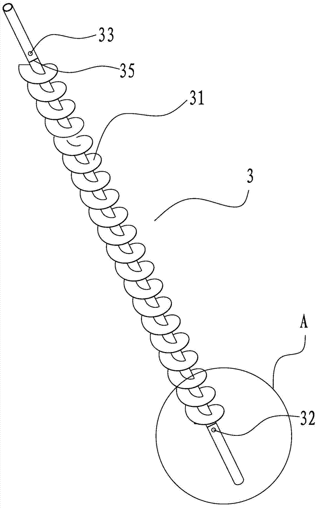
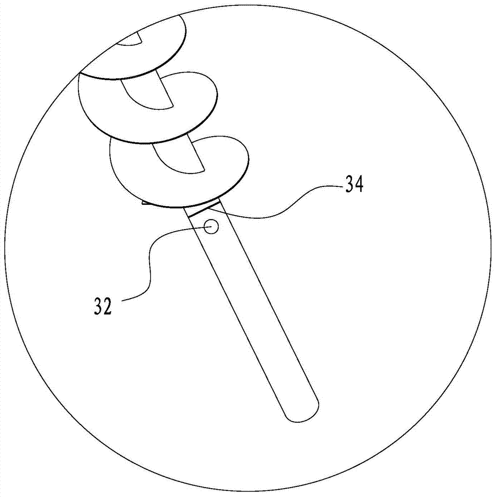
[0042] The central shaft 3 is sleeved in the intermediate sleeve 2 through a bearing 43. The outer wall of the central shaft 3 and the inner wall of the intermediate sleeve 2 form a first cavity. Both ends of the first cavity are respectively provided with first inlets and The first outlet; the intermediate sleeve 2 is sleeved in the housing 1, the housing 1 is provided with an outer end plate 12, the outer wall of the intermediate sleeve 2 and the housing 1 provided with the outer end plate 12 form a second cavity, The two ends of the housing 1 are respectively provided with a second inlet 13 and a second outlet 14; the outer wall of the central shaft 3 is provided with a spiral-shaped first partition 31 along the axial direction of the central shaft 3, such as figure 2 As shown, the outer wall of the intermed...


PUM


Abstract

The invention discloses a sludge drying device and method belonging to the technical field of sludge treatment. The device comprises a shell, a middle sleeve, a central shaft and a driving mechanism, wherein the central shaft is sleeved in the middle sleeve; a first chamber is formed by the outer wall of the central shaft and the inner wall of the middle sleeve; both ends of the first chamber are respectively provided with a first inlet and a first outlet; the middle sleeve is sleeved in the shell; a second chamber is formed by the outer wall of the middle sleeve and the inner wall of the shell; both ends of the shell are respectively provided with a second inlet and a second outlet; the outer wall of the central shaft is provided with a helical first partition board along the axial direction of the central shaft; the outer wall of the middle sleeve is provided with a helical second partition board along the axial direction of the middle sleeve; and the driving mechanism drives the middle sleeve to rotate along the axial direction thereof. According to the device and method disclosed by the invention, the heat exchange energy efficiency is increased, and the sludge treatment operating cost is reduced. The invention is low in initial cost and operating cost, can be widely applicable to industrial and municipal sludge treatment and has wide application prospects.

Description

Technical field [0001] The invention relates to a sludge treatment technology, in particular to a sludge drying device and method. Background technique [0002] Municipal sludge is an inevitable by-product of urban wastewater treatment and sewage treatment. It mainly comes from urban sludge treatment plants, street channel drainage, domestic sewage sludge, water supply plant sludge, urban water dredging sludge and urban construction site sludge Wait. With the improvement of the service level of municipal facilities in modern cities and the increase of urban population, the discharge of urban domestic sewage is also increasing, resulting in a large amount of sludge in the treatment of urban sludge. Even if the treatment rate of sludge is high, the output of urban sludge is currently higher than the treatment capacity. The development of world industrial production and the development of cities is also one of the reasons for the rapid increase in urban sludge production. Data sh...

Claims


Application Information

Patent Timeline
IPC IPC(8): C02F11/12C02F11/18
Inventor 殷立宝马晓茜徐齐胜余昭胜司广树
Owner ELECTRIC POWER RES INST OF GUANGDONG POWER GRID
Why Eureka
Try Eureka