Supercharge Your Innovation With Domain-Expert AI Agents!

Evaporation equipment and its evaporation method

A kind of equipment and evaporation technology, which is applied in the direction of vacuum evaporation plating, sputtering plating, ion implantation plating, etc., can solve the problem of small nozzle clogging, limit the maximum injection rate of the injection mechanism, and increase the failure rate of the injection mechanism evaporation equipment and other issues to achieve the effect of improving reliability

Active Publication Date: 2015-10-14
BOE TECH GRP CO LTD
View PDF7 Cites 0 Cited by
  • Summary
  • Abstract
  • Description
  • Claims
  • Application Information

AI Technical Summary

Problems solved by technology

However, on the one hand, this limits the maximum injection rate of the injection mechanism. On the other hand, because small nozzles are prone to clogging failures, it increases the failure rate of the injection mechanism and even the entire evaporation equipment.

Method used


Image

  • Evaporation equipment and its evaporation method
  • Evaporation equipment and its evaporation method
  • Evaporation equipment and its evaporation method

Examples


Embodiment Construction

[0030] The specific implementation manner of the present invention will be further described below in conjunction with the drawings and embodiments. The following examples are only used to illustrate the present invention, but not to limit the scope of the present invention.

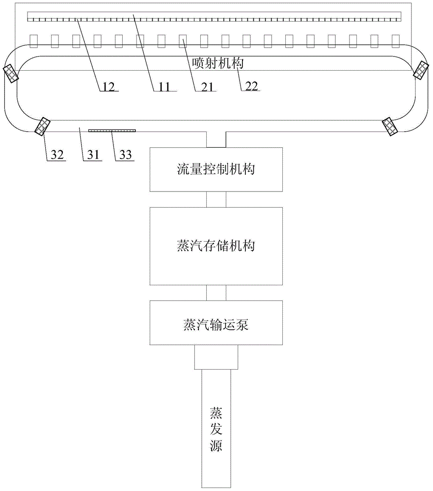
[0031] The evaporation equipment provided in this embodiment is as figure 2 shown in; the evaporation equipment includes an evaporation source, a steam circulation mechanism and an injection mechanism; wherein, the evaporation source is used to provide organic vapor; the steam circulation mechanism is used to circulate the organic vapor provided by the evaporation source; the injection mechanism and the steam cycle The mechanism is connected, and is used for spraying the organic vapor in the steam cycle mechanism onto the substrate 11 to form an organic coating. In this evaporation equipment, the organic vapor provided by the evaporation source is circulated by using the steam circulation mechanism, so...


PUM


Abstract

The invention relates to vapor deposition equipment and a vapor deposition method of the equipment. The vapor deposition equipment comprises an evaporation source, a steam circulation mechanism and an injection mechanism which are sequentially arranged, wherein the evaporation source is used for providing organic steam; the steam circulation mechanism is used for enabling the organic steam provided by the evaporation source to circulate and flow; the injection mechanism is communicated with the steam circulation mechanism to inject the organic steam in the steam circulation mechanism to an organic coating film formed on a substrate. The steam circulation mechanism is utilized to circulate the organic steam provided by the evaporation source, so as to uniformly provide the organic steam for each position of the injection mechanism as far as possible; nozzles at each position of the injection mechanism are configured to be identical, and the undersize or oversize nozzles are not required to be arranged, so that the problem that the injection mechanism is easy to block and break down is solved from the source, and the reliability of the vapor deposition equipment is greatly promoted.

Description

technical field [0001] The invention relates to the technical field of display device preparation, in particular to an evaporation device and an evaporation method thereof. Background technique [0002] OLED (Organic Light Emitting Diode, Organic Light Emitting Diode) display device has self-illumination, no backlight module, high contrast and definition, wide viewing angle, full curing, suitable for flexible panels, good temperature characteristics, low power consumption, A series of excellent characteristics such as fast response speed and low manufacturing cost have become one of the key development directions of a new generation of flat panel display devices, and thus attract more and more attention. [0003] In the prior art, the basic structure of an OLED display device includes an anode layer, a functional film layer, and a cathode layer; the above-mentioned functional film layer includes: a hole transport layer, an organic light-emitting layer, and an electron transp...

Claims


Application Information

Patent Timeline
Patent Type & Authority Patents(China)
IPC IPC(8): C23C14/24C23C14/12
Inventor 赵德江崔伟王路
Owner BOE TECH GRP CO LTD
Features
  • R&D
  • Intellectual Property
  • Life Sciences
  • Materials
  • Tech Scout
  • Unparalleled Data Quality
  • Higher Quality Content
  • 60% Fewer Hallucinations
Learn More