Shuttle core clamping mechanism used in automatic base line replacing device of embroidery machine

A clamping mechanism and technology for embroidery machines, which are applied to the mechanism of embroidery machines, embroidery machines, textiles and paper making, etc., can solve the problems of reducing the clamping force of bobbins, machine destructive accidents, and reducing work stability and reliability. , to achieve the effect of improving utilization and service life, improving reliability and stability, and extending trouble-free working time

Active Publication Date: 2014-04-02
FOSHAN QICHUANG TECH DEV
View PDF5 Cites 5 Cited by
  • Summary
  • Abstract
  • Description
  • Claims
  • Application Information

AI Technical Summary

Problems solved by technology

[0005] Since the bobbin can continue to be used only by rewinding the bobbin thread every time it is used up, the bobbin including the bobbin cover and the core are all reusable parts. During frequent replacement, the clamping process is normal. The accumulation of wear and the collision and drop during manual operation, together with the bobbin used, often have products from different manufacturers, and the quality of the bobbin (processing accuracy and wear resistance, etc.) is different, so that the bobbin cover The outer dimensions change gradually, generally within 1 to 2 months, the bobbin becomes obviously "old", and the consistency becomes poor, thus reducing the clamping force of the clamping mechanism on the bobbin
The most influential one is the loose leaf, which is the only moving part on the bobbin case. If the rotating shaft is worn or loosened, the opening angle of the loose leaf will become smaller, or the loose leaf will loosen up and down along the direction of the rotating shaft. The limiting plate and the raised clamp cylinder on it are fixed, and the above-mentioned changes of the loose-leaf make the loose-leaf unable to compress the limiting plate, and the clamping force of the claw and the limiting plate to the loose-leaf is greatly reduced, and The locking depth of the small cylindrical latch to the loose-leaf window becomes shallower, and it is more difficult to prevent the loose-leaf from moving up and down along the axis of rotation
In addition, the front end of the mounting plate of the bobbin clamping mechanism is arranged as a circular arc surface, which makes it difficult to make the bobbin close to the clamping mechanism when the clamping force is weakened
Due to the above problems, the consequence is that the bobbin will fall off when the situation is serious, and generally the bobbin will swing, so that the verticality of the side of the bobbin and the position of the center of the circle will deviate from the original state. When pushed into the rotary hook bed, it cannot be vertically inserted into the central axial core column of the rotary hook bed and is in a skewed state. In this way, it will cause abnormal wear of the parts, and cause destructive accidents of the machine
If the above-mentioned problems existing in the existing bobbin clamping mechanism cannot be effectively solved, there will be hidden dangers in the equipment, thereby reducing its working stability and reliability

Method used


Image

  • Shuttle core clamping mechanism used in automatic base line replacing device of embroidery machine
  • Shuttle core clamping mechanism used in automatic base line replacing device of embroidery machine
  • Shuttle core clamping mechanism used in automatic base line replacing device of embroidery machine

Examples


Embodiment Construction

[0020] The present invention is described in further detail by the following examples.

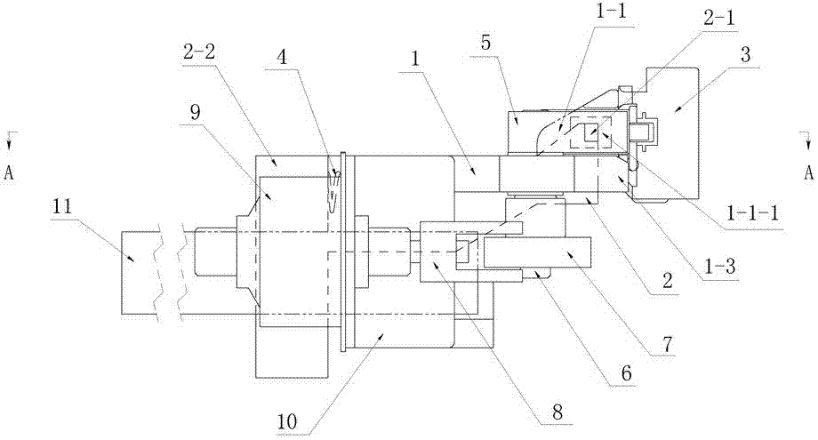
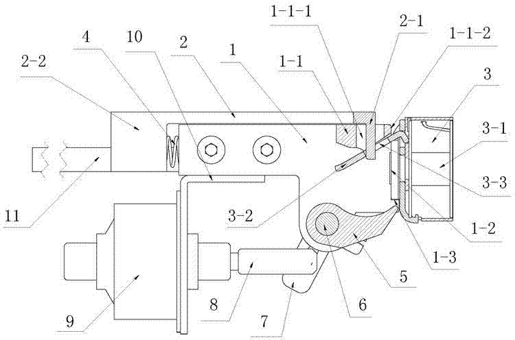
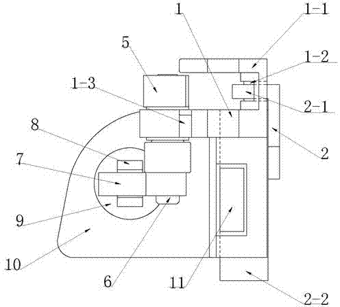
[0021] see Figure 1 ~ Figure 3 As shown, a bobbin clamping mechanism for the automatic bobbin thread changing device of an embroidery machine is composed of a claw frame 1, a dial angle limit frame 2, a buffer spring 4, a claw 5, a claw shaft 6, and a claw push arm 7 , motor shaft 8, thrust motor 9 and thrust motor frame 10 to form. Dialing angle limit frame 2 is fixedly connected with the bobbin access guide plate 11 on the bobbin thread changing device by the mounting seat 2-2 at its left end, to drive the integral left and right movement of the bobbin clamping mechanism. The claw frame 1 is slidably connected with the dial angle limit frame 2 through the guide rail, and a buffer spring 4 is provided between the claw frame 1 and the mounting seat 2-2 to play a buffering role when accessing the bobbin. Cooperate with the clamping loose-leaf 3-2 during the core; the finger 5 for opening...


PUM


Abstract

The invention discloses a shuttle core clamping mechanism used in an automatic base line replacing device of an embroidery machine. The shuttle core clamping mechanism consists of a shifting claw rack, a shifting angle limiting rack, a buffer spring, a shifting claw, a shifting claw shaft, a shifting claw push arm, a motor shaft, a thrust motor and a thrust motor rack, wherein the shifting angle limiting rack with a hinge hook at the right end is connected with the shifting claw rack in a sliding manner; the buffer spring is arranged between the shifting claw rack and a mounting base; one end of the shifting claw shaft is fixedly connected with the shifting claw; the other end of the shifting claw shaft penetrates through the shifting claw rack and is fixedly connected with one end of the shifting claw push arm; the outer end of the motor shaft is connected with a guide groove of the shifting claw push arm in a sliding manner; the shifting claw, the hinge hook and a hinge are in contact connection; the shifting angle limiting rack is fixedly connected with a shuttle core access guide plate. By adopting the shuttle core clamping mechanism, a shuttle core can be firmly clamped and is kept be in correct posture when being stored and moved, so that abrasion on components and destructive accidents are effectively reduced.

Description

technical field [0001] The invention relates to the technical field of bobbin thread changing for embroidery machines, in particular to a bobbin clamping mechanism for an automatic bobbin thread changing device for embroidery machines. Background technique [0002] The automatic bobbin thread changing device on the embroidery machine is used to replace the bobbin thread bobbin on the rotary hook with the applicable bobbin when the bobbin thread built in the rotary hook of the embroidery machine head is used up or needs to be replaced with a different color bobbin thread. Automatic replacement. The rotary hook of the embroidery machine is installed in the rotary hook box under each machine head, and consists of a rotary hook bed and a bobbin. The rotary hook bed is installed in the rotary hook box, and the bobbin is set on the central axial core post of the rotary hook bed. The bobbin includes the bobbin cover and the thread core, which can be taken out and put in from the ...

Claims


Application Information

Patent Timeline
Patent Type & Authority Applications(China)
IPC IPC(8): D05C11/16
Inventor 梁国杰
Owner FOSHAN QICHUANG TECH DEV
Why Eureka
Try Eureka