Centrifugal fan impeller

A centrifugal fan and impeller technology, applied in mechanical equipment, machines/engines, liquid fuel engines, etc., can solve the problems of jet-wake at the outlet of the impeller, increased noise, etc., to reduce aerodynamic noise, increase distance, and suppress disturbances Effect

Inactive Publication Date: 2014-04-02
NINGBO FOTILE KITCHEN WARE CO LTD
View PDF9 Cites 23 Cited by
  • Summary
  • Abstract
  • Description
  • Claims
  • Application Information

AI Technical Summary

Problems solved by technology

[0004] The above-mentioned impeller adopts straight blades, and the blade path adopts accelerated blade path. During the operation of the fan, especially in the low-flow and high-speed working conditions used by users, the phenomenon of "jet-wake" is easy to form at the outlet of the impeller, resulting in increased noise.

Method used


Image

  • Centrifugal fan impeller
  • Centrifugal fan impeller
  • Centrifugal fan impeller

Examples


Embodiment 1

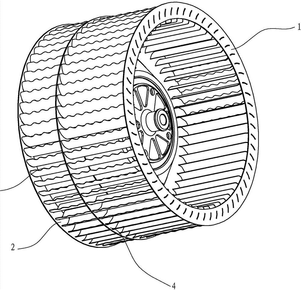
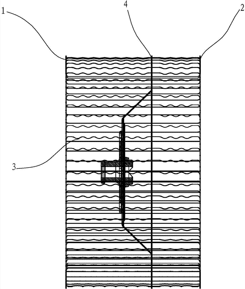
[0019] see figure 1 with figure 2 , an impeller of a centrifugal fan, including a front ring 1 and a rear ring 2, a plurality of blades 3 are fixed between the front ring 1 and the rear ring 2, and the blades 3 are riveted with the front ring 1 and the rear ring 2 in an existing conventional way fixed together. A middle plate 4 is also provided between the front ring 1 and the rear ring 2, thereby forming a two-way air intake structure.

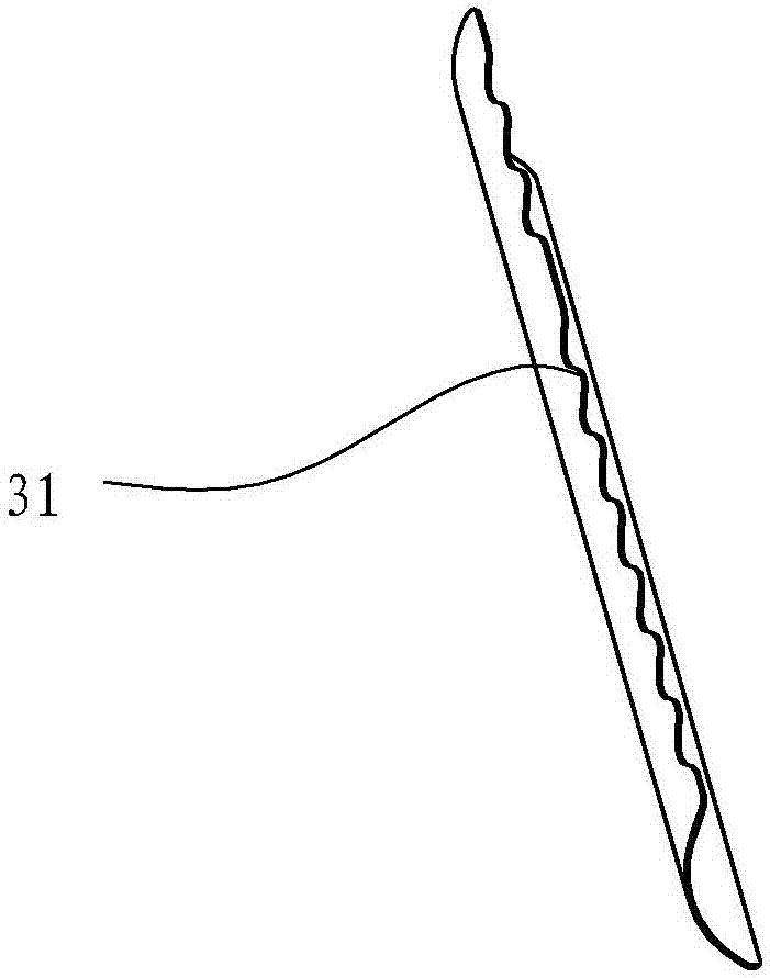
[0020] see image 3 , the outlet end 31 of the blade 3 (the trailing edge towards the outside of the impeller) is wavy and serrated; see Figure 4 , the outlet end 31 of the blade 3 includes a plurality of sawtooth 311, the sawtooth 311 is arranged along the length extension direction of the blade 3, the height of each sawtooth 311 is h, and the width is t, preferably, 0.5mm

[0021] The blade 3 is divided into front and rear two sections at the middle plate 4, the distance from the startin...

Embodiment 2

[0023] see Figure 5 , the difference between this embodiment and Embodiment 1 is that the centrifugal fan is a single-inlet type, and no middle disk is provided. The distance of 1 is a, and the distance between the end of the last sawtooth 311 (the sawtooth near the back circle 2) and the back circle 2 is b, preferably, 0<


PUM


Abstract

The invention discloses a centrifugal fan impeller, which comprises a front ring and a back ring, wherein a plurality of blades are fixedly arranged between the front ring and the back ring. The centrifugal fan impeller is characterized in that the outlet ends of the blades form a wave-shaped sawtooth type by a plurality of sawteeth. The outlet ends (tail edges) of the blades are provided with structures in the wave-shaped sawtooth type, and the wake vortex shedding positions of the tail edges of the blades are changed, so the distance between the vortex centers is increased, the disturbance of the shedding vortex on the wake flowing is inhabited, and the pneumatic noise caused by the wake vortex and the unsteady pressure fluctuation of the blade surfaces is further reduced. The height and the width of the sawteeth are limited, the noise is further reduced, and the influence of the sawteeth on the pressure and air quantity reduction of a fan can also be reduced.

Description

technical field [0001] The invention relates to a centrifugal fan, in particular to an impeller of the centrifugal fan. Background technique [0002] Range hoods have become one of the indispensable kitchen appliances in modern families. Generally, range hoods include a fume collection hood, a fan housing on the fume collection hood, and a fan housing including a volute, an impeller and a driving impeller is installed in the fan housing. Motor centrifugal fan. [0003] And the impeller of the centrifugal fan commonly used at present is the straight blade of circular arc plate, as the Chinese patent application number 200810059095.9 discloses a double-sided uniform air inlet fan system for range hoods, including a main engine, an impeller and a fan, and the impeller includes an upper ring , middle ring, bottom ring and blades; another example is an impeller with a middle disk structure disclosed in the applicant’s Chinese patent application number 201120024842.2, which has a...

Claims


Application Information

Patent Timeline
Patent Type & Authority Applications(China)
IPC IPC(8): F04D29/28F04D29/30
Inventor 梁之博胡承杰任树栋李斌茅忠群诸永定
Owner NINGBO FOTILE KITCHEN WARE CO LTD
Why Eureka
Try Eureka