Pharmaceutical drier

A dryer and drying chamber technology, applied in the direction of dryers, drying, drying solid materials, etc., can solve the problems of increased drying costs, decomposition of active ingredients, and errors in temperature control, so as to improve the drying effect , reduce thermal decomposition, improve the quality of the effect

Inactive Publication Date: 2014-04-02
GUANGXI NANNING BAIHUI PHARMA GRP
View PDF5 Cites 1 Cited by
  • Summary
  • Abstract
  • Description
  • Claims
  • Application Information

AI Technical Summary

Problems solved by technology

The dryer with this structure has the following defects: direct heating can easily lead to the decomposition of some active ingredients in the material; the material spread on the material tray is not heated evenly, resulting in increased drying costs or poor drying effect; continuous drying cannot be achieved. The drying operation; there is an error in the temperature control, and the drying effect is not ideal

Method used


Image

  • Pharmaceutical drier

Examples


Embodiment 1

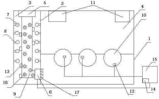
[0020] The dryer includes a shell 1, the partition 2 divides the shell 1 into a hot air chamber 3 and a drying chamber 4, and a hot air blower 5 is installed below the air inlet of the hot air chamber 3 to blow hot air from the hot air chamber 3 to the drying chamber 4. An air intake fan 6 is provided on the partition plate 2 between the hot air chamber 3 and the drying chamber 4, and an air intake regulating valve 17 is provided on the air intake fan 6. The inner wall of the hot air chamber 3 is evenly distributed with metal pendants 7, and the metal pendants 7 are suspended and fixed with electric heating tubes 8 that are uniformly distributed and heated facing the material delivery tank. A power regulating device 14 is used for adjustment. A material conveying trough 9 and two temperature sensors 13 arranged beside the material conveying trough 9 are arranged in the hot air chamber 3 . The temperature sensors 13 are connected with the control cabinet 15 . The bottom of the ...

Embodiment 2

[0022] The dryer includes a shell 1, the partition 2 divides the shell 1 into a hot air chamber 3 and a drying chamber 4, and a hot air blower 5 is installed below the air inlet of the hot air chamber 3 to blow hot air from the hot air chamber 3 to the drying chamber 4. The partition plate 2 between the hot air chamber 3 and the drying chamber 4 is provided with an air inlet fan 6, and the air inlet fan 6 is provided with an air inlet regulating valve 17, which can adjust the direction and angle of the air outlet. The inner wall of the hot air chamber 3 is evenly distributed with metal pendants 7, and the metal pendants 7 are suspended and fixed with electric heating tubes 8 that are uniformly distributed and heated facing the material delivery tank. The power adjustment device 14 is used for adjustment. The hot air chamber 3 is provided with two material conveying troughs 9 and two temperature sensors 13 arranged beside the material conveying troughs 9 . The bottom of the mat...

Embodiment 3

[0024] The dryer includes a shell 1, the partition 2 divides the shell 1 into a hot air chamber 3 and a drying chamber 4, and a hot air blower 5 is installed below the air inlet of the hot air chamber 3 to blow hot air from the hot air chamber 3 to the drying chamber 4. The partition plate 2 between the hot air chamber 3 and the drying chamber 4 is provided with an air inlet fan 6, and the air inlet fan 6 is provided with an air inlet regulating valve 17, which can adjust the direction and angle of the air outlet. The inner wall of the hot air chamber 3 is evenly distributed with metal pendants 7, and the metal pendants 7 are suspended and fixed with electric heating tubes 8 that are uniformly distributed and heated facing the material delivery tank. The power adjustment device 14 is used for adjustment. The hot air chamber 3 is provided with three material conveying troughs 9 and eight temperature sensors 13 arranged beside the material conveying troughs 9 . The bottom of the...


PUM


Abstract

The invention discloses a pharmaceutical drier, comprising a shell, wherein the internal of the shell is divided into a hot air chamber and a drying chamber by a partition, the lower part of the partition is provided with a hot air blower blowing from the hot air chamber to the drying chamber, the top of the hot air chamber is provided with an intake fan, a plurality of material conveying troughs are arranged in the drying chamber, a spiral conveyer is mounted in the material conveying trough, the top of the drying chamber is provided with a dehumidifying fan, metal pendants are uniformly distributed on the inner wall of the hot air chamber, electric heating pipes are fixed on the metal pendants in a hanging manner, the electric heating pipes are uniformly distributed and provided with heating surfaces facing the material conveying troughs, and the hot air chamber is further provided with a temperature sensor and a electric heating pipe power regulating device. According to the pharmaceutical drier, the material can be continuously dried, so that the drying effect is improved, thermal decomposition of effective constituents in the material is reduced, and the quality of finished product is improved.

Description

technical field [0001] The invention relates to the field of pharmaceutical technology, in particular to a dryer used in the pharmaceutical industry. Background technique [0002] At present, in the pharmaceutical industry, in order to meet the production needs of the next process as soon as possible, the materials are usually dried by using a dryer to speed up the drying speed of the materials and shorten the material supply cycle between processes. In the production process of some pharmaceuticals or their intermediate products, the drying step is very critical. The drying time, drying uniformity, and drying temperature control directly affect the drying effect of the product. The effect is one of the most important factors in the quality of the product. Therefore, the pharmaceutical industry needs a medicine dryer with good drying effect and without greatly increasing the production cost. [0003] Most of the existing dryers have a relatively simple structure, and t...

Claims


Application Information

Patent Timeline
IPC IPC(8): F26B17/18F26B21/00F26B25/04
Inventor 周健黄斌
Owner GUANGXI NANNING BAIHUI PHARMA GRP
Why Eureka
Try Eureka