A precision pinhole alignment debugging system and method

A precision pinhole and debugging system technology, applied in optical components, optics, instruments, etc., can solve the problems of the system not working and focused light not passing through the pinhole, etc., and achieve the effect of intuitive debugging process, wide applicability, and rapid construction

Active Publication Date: 2016-01-27
SUZHOU INST OF BIOMEDICAL ENG & TECH CHINESE ACADEMY OF SCI
View PDF6 Cites 0 Cited by
  • Summary
  • Abstract
  • Description
  • Claims
  • Application Information

AI Technical Summary

Problems solved by technology
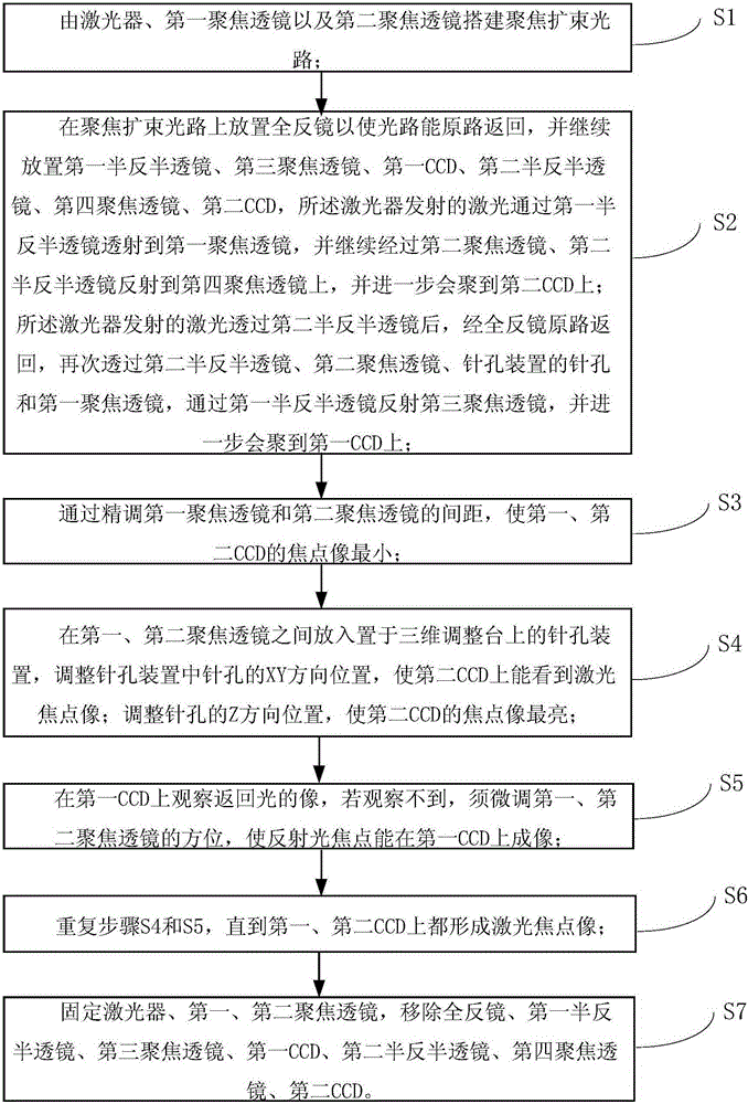
At the same time, a small change in the direction of the incident light in the optical path will also cause the focused light to fail to pass through the pinhole, and the system cannot work. This puts more demands on the on-site adjustment and timely correction of the pinhole alignment device

Method used


Image

  • A precision pinhole alignment debugging system and method
  • A precision pinhole alignment debugging system and method

Examples


Embodiment Construction

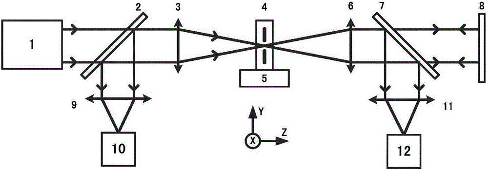
[0029] Please refer to figure 1 , figure 1 A schematic structural diagram of a precision pinhole alignment debugging system provided by an embodiment of the present invention.

[0030] The present invention provides a precision pinhole alignment debugging system, which includes a laser 1, a first half-mirror 2, a second half-mirror 7, a first focusing lens 3, a second focusing lens 6, a third focusing Lens 9 , fourth focusing lens 11 , pinhole device 4 , three-dimensional adjustment stage 5 , total reflection mirror 8 , first CCD10 and second CCD12 . Wherein, the pinhole device 4 includes a pinhole (not shown) and a tooling (not shown), and the three-dimensional adjustment table 5 adjusts the direction position of the pinhole in the pinhole device 4 .

[0031] The laser 1 , the first focusing lens 3 and the second focusing lens 6 build a focusing beam expanding optical path, and the total mirror 8 is placed on the focusing beam expanding optical path so that the optical path...


PUM


Abstract

The invention relates to the technical field of optical precise adjustment, and provides a precise pinhole alignment debugging method. With the method, components such as a laser, a first semi-reflection semi-transparent mirror, a second semi-reflection semi-transparent mirror, a first focusing lens, a second focusing lens, a third focusing lens, a fourth focusing lens, a pinhole device, a three-dimensional adjustment table, a total-reflection mirror, a first CCD (charge coupled device) and a second CCD are adopted to carry out alignment debugging on a precise pinhole so as to realize precise spatial filter adjustment. In addition, the invention also provides a precise pinhole alignment debugging system.

Description

technical field [0001] The invention relates to the technical field of optical precision adjustment, in particular to a precision pinhole alignment adjustment system and method. Background technique [0002] Precision pinhole alignment technology refers to accurately placing a micron-sized pinhole at the focal point of an optical lens, usually the coincident focus of two optical lenses, that is, the beam is focused and then expanded through the pinhole. The precisely aligned pinholes can perform precise spatial filtering for the optical path, modify the laser mode, adjust the divergence angle, filter out stray light, etc., and are widely used in various precision optical devices and instruments. [0003] The precision pinhole alignment technology usually requires alignment accuracy of more than 1 / 10 of the pinhole size, that is, the three-dimensional positioning accuracy of pinhole positioning is on the order of micron or submicron, which is difficult to guarantee in the des...

Claims


Application Information

Patent Timeline
Patent Type & Authority Patents(China)
IPC IPC(8): G02B27/30
Inventor 孔晨晖张运海
Owner SUZHOU INST OF BIOMEDICAL ENG & TECH CHINESE ACADEMY OF SCI
Why Eureka
Try Eureka