Distributed RTU (Remote Terminal Unit) system

A distributed, CAN bus technology, applied in the direction of comprehensive factory control, comprehensive factory control, electrical program control, etc., can solve the problems of complex monitoring field wiring methods, increased maintenance and upgrade costs, and increased labor costs, so as to reduce later maintenance and upgrades Lower cost, convenient on-site maintenance and debugging, and reduced work load

Inactive Publication Date: 2014-04-02
山东三龙智能技术有限公司
View PDF6 Cites 6 Cited by
  • Summary
  • Abstract
  • Description
  • Claims
  • Application Information

AI Technical Summary

Problems solved by technology

At present, RTU mainly uses a single MCU in the monitoring of the water supply network. The MCU not only manages the on-site sensors and controls the actuators, but also undertakes the task of communicating with the upper computer management system, which may easily cause the MCU to be overloaded; especially for multi-site, multi- The on-site wiring method for parameter monitoring is complicated, which increases labor costs; additional RTU equipment is required for additional sites in the later period, and wiring is re-routed, which increases maintenance and upgrade costs; DTU communication modules need to be placed in each RTU equipment, which increases equipment costs

Method used


Image

  • Distributed RTU (Remote Terminal Unit) system
  • Distributed RTU (Remote Terminal Unit) system
  • Distributed RTU (Remote Terminal Unit) system

Examples


Embodiment Construction

[0014] In order to clearly illustrate the technical features of this solution, the present invention will be described in detail below through specific implementation modes and in conjunction with the accompanying drawings.

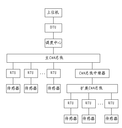
[0015] Such as figure 1 Shown, a kind of distributed RTU system of the present invention, it comprises upper computer, master controller, DTU, main CAN bus, expansion CAN bus, CAN bus repeater, some RTUs and some sensors, described RTU and on-site The sensor is connected to the field device and is connected to the main CAN bus or the extended CAN bus. The extended CAN bus is connected to the main CAN bus through a CAN bus repeater. The main CAN bus is connected to the main controller. The main controller Connect with the host computer through DTU.

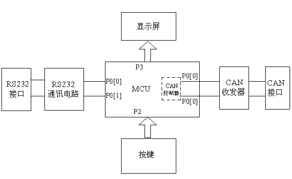
[0016] Such as figure 2 As shown, the main controller of the present invention includes MCU, CAN transceiver, CAN interface, RS232 interface, RS232 communication circuit, display screen and buttons, and the...


PUM


Abstract

The invention discloses a distributed RTU (Remote Terminal Unit) system, which comprises a host, a main controller, a DTU (Data Transfer Unit), a main CAN (Controller Area Network) bus, an extension CAN bus, a CAN bus relay, a plurality of RUTs and a plurality of sensors, wherein the RTUs are connected with a field sensor and field equipment, and are connected with the main CAN bus or the extension CAN bus; the extension CAN bus is connected with the main CAN bus through the CAN bus relay; the main CAN bus is connected with the main controller; the main controller is connected with the host through the DTUs. By adopting the distributed RTU system, the workload of the MCU of the main controller is reduced, the wiring complexity is lowered, subsequent maintenance and upgrade costs are reduced, and the equipment cost is reduced. The running state of each station can be monitored, and the RTU of each station can be controlled, so that convenience is brought to field maintenance and debugging.

Description

technical field [0001] The invention relates to a remote control system, in particular to a distributed RTU system applied in the field of water supply pipe network monitoring, which belongs to the technical field of water conservancy resources. Background technique [0002] RTU is a device that can automatically complete the collection, storage, transmission and control of hydrological (water regime, water resources) parameters. In pipe network monitoring, RTU is mainly used for water metering, pressure measurement and providing on-site data for pipe network monitoring. At present, RTU mainly uses a single MCU in the monitoring of the water supply network. The MCU not only manages the on-site sensors and controls the actuators, but also undertakes the task of communicating with the upper computer management system, which may easily cause the MCU to be overloaded; especially for multi-site, multi- The on-site wiring method of parameter monitoring is complicated, which incre...

Claims


Application Information

Patent Timeline
Patent Type & Authority Applications(China)
IPC IPC(8): G05B19/418
CPCY02P90/02
Inventor 王伟周圣仓
Owner 山东三龙智能技术有限公司
Why Eureka
Try Eureka