Blade server oriented box-sleeving type heat preservation/heat dissipation device

A blade server and cooling device technology, used in cooling/ventilation/heating renovation, instruments, electrical digital data processing, etc. And the fastening is simple and reliable, the structure is simple and compact, and the effect of improving the heat dissipation efficiency

Active Publication Date: 2014-04-02
NO 709 RES INST OF CHINA SHIPBUILDING IND CORP
View PDF5 Cites 5 Cited by
  • Summary
  • Abstract
  • Description
  • Claims
  • Application Information

AI Technical Summary

Problems solved by technology

Commercial servers usually use forced air cooling through the front and back, but this method cannot be used in harsh environments. When the environmental conditions are humid or contain corrosive substances such as mold and salt spray, a closed structure must be used to separate the circuit board from the harsh environment. Environmental isolation, but this makes heat dissipation difficult
In this case, in order to obtain a good heat dissipation effect, when the power dissipation of the equipment is too large, the industry usually considers the use of water cooling to solve the heat dissipation problem, but the water cooling method is limited by external conditions, such as: there must be a water source If you use self-circulating water, you have to bring your own water tank pump, water pipeline, cooling device, etc. For some small and medium-sized servers, it is difficult to implement
Moreover, there is a hidden danger of water leakage in water cooling, and its safety needs to be considered
[0003] In addition, the storage device in the server is not suitable for low temperature operation, so preheating measures are required, but heating and heat dissipation are often contradictory, because usually good heat preservation effect means poor heat dissipation effect

Method used


Image

  • Blade server oriented box-sleeving type heat preservation/heat dissipation device
  • Blade server oriented box-sleeving type heat preservation/heat dissipation device
  • Blade server oriented box-sleeving type heat preservation/heat dissipation device

Examples


Embodiment Construction

[0022] The present invention will be further described in detail below in conjunction with the drawings:

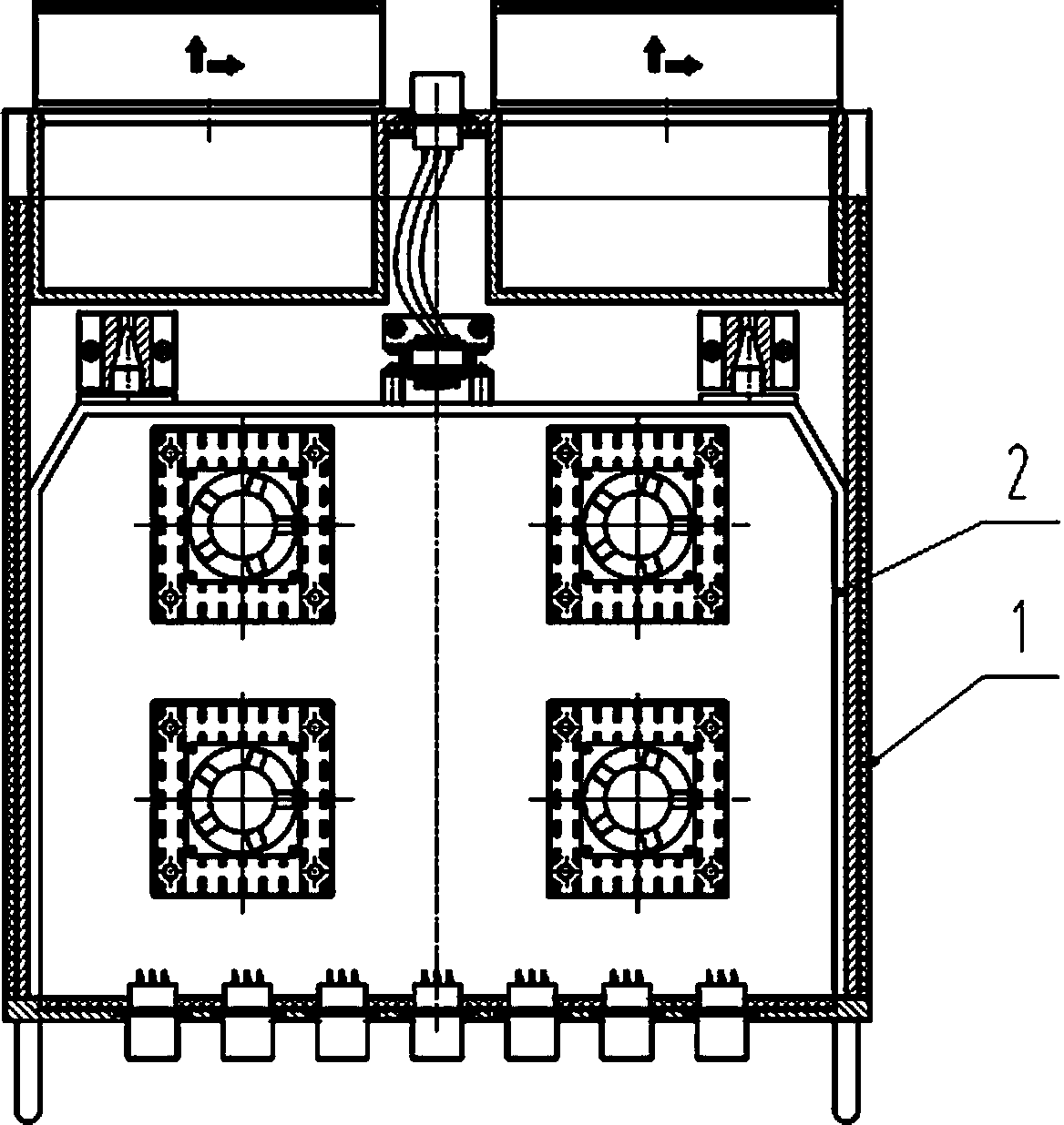
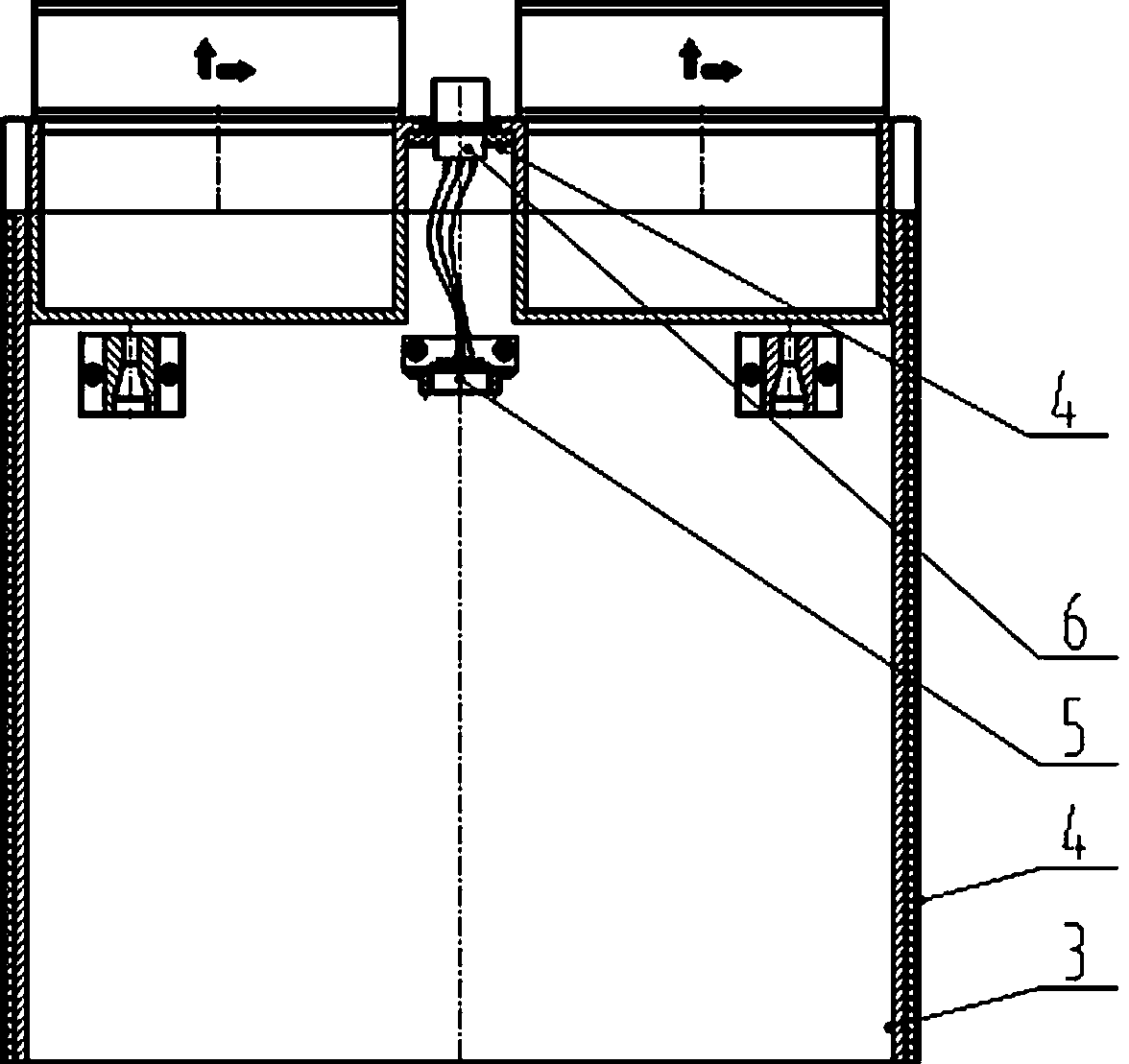
[0023] Such as Figure 1 ~ Figure 6 As shown, a box-type heat preservation / heat dissipation device for blade servers of the present invention is composed of an outer box 1 and an inner box 2. The inner box 2 and the outer box 1 pass through the conical guide at the tail of the inner box 2 The positioning pin 16 is fixed with the screws on the front panel 13 of the inner box.

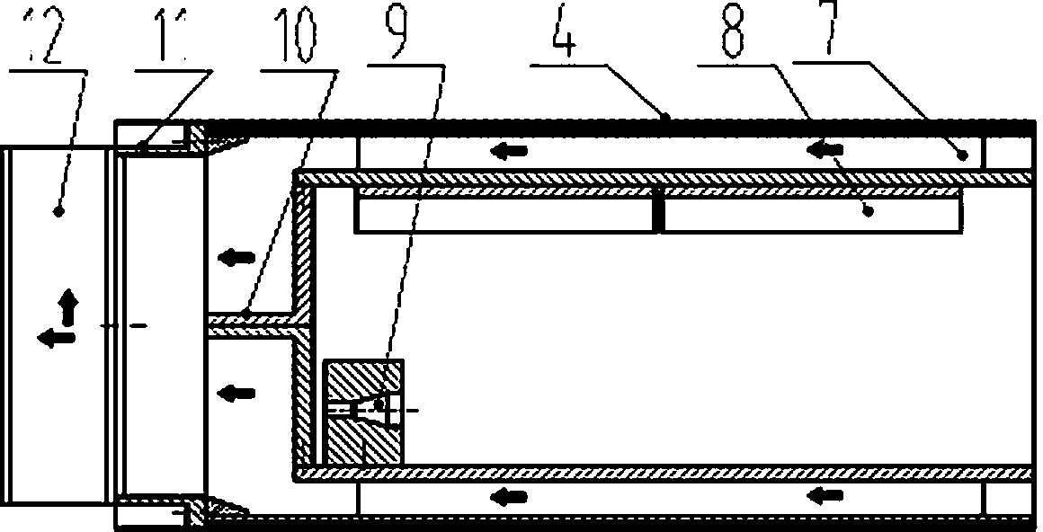
[0024] The outer box 1 is a heat-preserving / heat-dissipating box body, including: side plates 3, heat-insulating plates 4, collision-type adapter sockets 5, external connectors 6, air duct plates 7, finned radiators 8, and conical shapes Positioning pin seat 9, air box 10, confluence wind box 11, external fan 12; the upper and lower sides of outer box 1 are composed of air duct plate 7 and heat insulation plate 4, air duct plate 7 is on the inside, and heat insulation plate 4 is on the outside ; The fi...


PUM


Abstract

Disclosed is a blade server oriented box-sleeving type heat preservation / heat dissipation device. An inner-outer box sleeving structure is adopted, an inner box is an electrical appliance bearing box body, and an outer box is a heat preservation / heat dissipation box body. An upper and a lower flat surface of the outer box of the device are air duct heat preservation / heat transfer surfaces, the rest surfaces are heat insulation surfaces, heat dissipation and heat preservation of a case are controlled by controlling on and off of air flow in upper and lower heat transfer air ducts, and finished product heat dissipators are arranged on an upper air duct plate by surface mounting to enlarge a heating surface of the outer box so as to improve heat dissipation efficiency. Heating chips in the inner box adopt an upward convection and downward conduction dual-path heat transfer mode to lower heat flux and improve heat transfer efficiency. The inner box and the outer box are separated and fastened by means of separation and reunion of taper pin holes. The device takes economical and safe natural air as a heat transfer medium, and has a safe, energy-saving and compact heat preservation / heat dissipation function without depending on cooling facilities but by structural design.

Description

Technical field [0001] The present invention relates to the technical field of electronic heat dissipation, in particular to a box-type heat preservation / heat dissipation device for blade servers. Background technique [0002] The blade server is characterized by a large plane size and a small thickness. As the blade server has strong data processing and storage capabilities, it consumes a lot of heat accordingly. Commercial servers usually adopt a forced air cooling method that runs through the front and back, but this method cannot be used in harsh environments. When the environmental conditions are humid or contain corrosive substances such as mold and salt spray, a closed structure must be adopted to protect the circuit board from the harsh environment. Environmental isolation, but this brings difficulties to heat dissipation. In this case, in order to obtain a good heat dissipation effect, when the dissipated power of the device is too large, the industry usually considers ...

Claims


Application Information

Patent Timeline
Patent Type & Authority Applications(China)
IPC IPC(8): G06F1/20H05K7/20
CPCY02D10/00
Inventor 严红陈艳华
Owner NO 709 RES INST OF CHINA SHIPBUILDING IND CORP
Why Eureka
Try Eureka