Planar antenna capable of switching wave beam for omnidirectional scanning within horizontal range

A planar antenna and range technology, applied in the electronic field, can solve the problem of not being able to achieve full coverage of the antenna, and achieve the effect of stable working status

Inactive Publication Date: 2014-04-02
UNIV OF ELECTRONICS SCI & TECH OF CHINA
View PDF3 Cites 27 Cited by
  • Summary
  • Abstract
  • Description
  • Claims
  • Application Information

AI Technical Summary

Problems solved by technology

This antenna can realize beam switching in four directions in the plane where the antenna is located, but since the 3dB beam width of the E plane of each beam state of the antenna is about 60°, there is a dead zone of about 120° in this plane, which cannot be realized Full coverage on the plane where the antenna is located

Method used


Image

  • Planar antenna capable of switching wave beam for omnidirectional scanning within horizontal range
  • Planar antenna capable of switching wave beam for omnidirectional scanning within horizontal range
  • Planar antenna capable of switching wave beam for omnidirectional scanning within horizontal range

Examples


Embodiment Construction

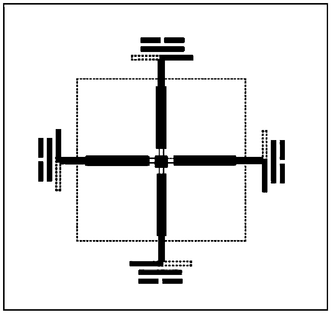
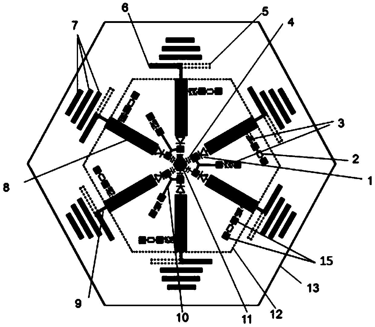
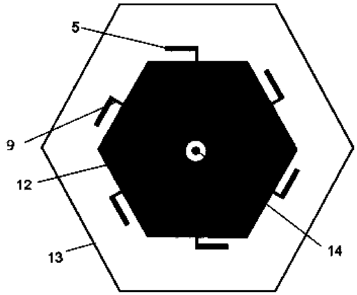
[0022] In this embodiment, a planar antenna whose central working frequency is within a horizontal range of 5.5 GHz and whose beams can be switched omnidirectionally is taken as an example.

[0023] Such as figure 2 , image 3 , Figure 4 As shown, the insulating substrate 13 is a polytetrafluoroethylene regular hexagonal substrate with a relative dielectric constant of 2.65, a thickness of 0.8 mm, and a side length of 72 mm. The metal ground plate 12 is a regular hexagonal ground plate with a side length of 32 mm corresponding to the insulating substrate. The central regular hexagonal feed patch 11 has a side length of 3mm, the patch feeder 8 (length×width) is 19.5×4.4mm, the feeder 9 (length×width) is 8×0.7mm, and the high impedance line 10 (length×width) ) is 11×0.4mm, the drive vibrator 5, 6 (length×width) is 12.2×1.8mm, and the director 7 (length×width) is 15.4×2mm, 14×2mm, 11.7×2mm from inside to outside, The distance between the directors is 2 mm, and the distance b...


PUM


Abstract

The invention provides a planar antenna capable of switching wave beams for omnidirectional scanning within a horizontal range. The antenna comprises an insulated substrate with a feed input port, a metallic grounding plate which is arranged on the lower surface of the substrate, emitters which are arranged on the upper surface of the substrate, control circuits of the emitters and a feed patch. By taking the feed patch as a center, the insulated substrate is equally divided into six areas; a control circuit is arranged in each area; one end of each control circuit is connected with the feed patch in the center through a blocking condense,r and the other end of each control circuit is connected with one emitter through a feeder; therefore, a relatively independent unit antenna is formed in each area. By switching the wave beams to cover the plane of the entire antenna, the whole coverage on the plane of the antenna is realized; since parameters except the radiation direction of each wave beam in the working state are consistent, the working state of the antenna provided by the invention is stable.

Description

technical field [0001] The invention belongs to the field of electronic technology, in particular to the beam switchable antenna technology with a PIN diode switch. Background technique [0002] As more and more information content needs to be transmitted, modern communication systems have higher and higher requirements on the information transmission rate in wireless communication, but due to the existence of multipath fading, the data transmission rate decreases with the increase of signal transmission distance . Numerous studies have shown that the proper use of antennas with switchable beams is one way to solve this problem. The pattern reconfigurable antenna can change the pattern of the transmitting and receiving antennas in real time according to changes in the communication environment, thereby effectively reducing noise interference, combating multipath fading, and improving the information transmission rate. [0003] A pattern reconfigurable printed quasi-Yagi an...

Claims


Application Information

Patent Timeline
Patent Type & Authority Applications(China)
IPC IPC(8): H01Q3/24
Inventor 王任王秉中丁霄
Owner UNIV OF ELECTRONICS SCI & TECH OF CHINA
Why Eureka
Try Eureka