Pneumatic terminal machine

A terminal machine and frame technology, applied in the direction of electrical components, circuits, connections, etc., can solve the problems of crimping terminals that are not suitable for small batches and multiple varieties, and achieve the effects of low cost, continuous operation, and high efficiency

Inactive Publication Date: 2014-04-02
WUHU SHUNCHENG ELECTRONICS
View PDF5 Cites 6 Cited by
  • Summary
  • Abstract
  • Description
  • Claims
  • Application Information

AI Technical Summary

Problems solved by technology

Existing fully automatic equipment is not suitable for small-batch and multi-variety terminal cri...

Method used


Image

  • Pneumatic terminal machine

Examples


Embodiment Construction

[0010] The preferred technical solutions of the present invention will be described in detail below in conjunction with the accompanying drawings.

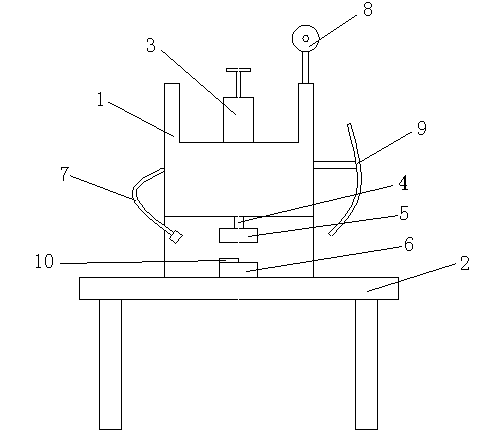
[0011] As shown in the figure, the pneumatic terminal machine of the present invention includes a frame 1, a workbench 2 and a feeding mechanism. The cylinder 3 is connected above the frame 1, and the cylinder 3 drives the punch 4 below it to move. The die upper die 5 is fixedly connected under the punch 4, the frame 1 is fixed on the workbench 2, the side of the frame 1 is also provided with an illuminating lamp 7, and the mold lower die 6 is fixed on the workbench 2 , and is located at the corresponding position below the upper die 5 of the mold, a positioning block 10 is arranged on the lower die 6 of the mold, the feeding mechanism is located on one side of the frame 1, and the feeding mechanism includes Discharging rack 8 and guide plate 9, described discharging rack 8 is fixed on the top of described frame 1, and described g...


PUM


Abstract

The invention discloses a pneumatic terminal machine. The pneumatic terminal machine comprises a frame, a workbench and a feeding mechanism, wherein an air cylinder is connected with the upper part of the frame; the air cylinder drives a punch below the air cylinder to move; an die upper die is fixedly connected with the lower part of the punch; the frame is fixed on the workbench; a die lower die is fixed on the workbench and positioned in a corresponding position below the die upper die; a positioning blocking piece is arranged on the die lower die; the feeding mechanism is positioned on one side of the frame. The pneumatic terminal machine is convenient and practical, can be operated continuously, has high efficiency, is low in cost, is applied to the pressure welding machining of a small amount of various of terminals, and is also applicable to the pressure welding of terminals required to be reworked.

Description

technical field [0001] The invention relates to the technical field of mechanical equipment, in particular to a pneumatic terminal machine. Background technique [0002] With the development of the economy, industries such as electronics, automobiles, communications, and electric power are developing rapidly, and these industries require a large number of wire harness products. Terminal crimping is a necessary step in the production process of wire harness products. Existing fully automatic equipment is not suitable for small-batch and multi-variety terminal crimping processing, and some operations that require rework also require suitable equipment for processing. Contents of the invention [0003] The purpose of the present invention is to provide a pneumatic terminal machine suitable for terminal crimping operation of small batches and varieties. [0004] In order to solve the above technical problems, the present invention provides a pneumatic terminal machine, which ...

Claims


Application Information

Patent Timeline
IPC IPC(8): H01R43/048H01R43/055
Inventor 杨自强田春连曹彩云
Owner WUHU SHUNCHENG ELECTRONICS
Why Eureka
Try Eureka