
Switching power supply with constant on-time control, and control circuit and control method for switching power supply

A switching power supply and control circuit technology, applied in control/regulation systems, high-efficiency power electronic conversion, electrical components, etc., can solve the problem of high switching loss of high-side switching tube HS, adverse effects of switching power supply efficiency, and switching power supply output voltage ripple It can shorten the discharge time, improve the efficiency, and reduce the output voltage ripple.

Active Publication Date: 2014-04-02
CHENGDU MONOLITHIC POWER SYST
View PDF3 Cites 13 Cited by
  • Summary
  • Abstract
  • Description
  • Claims
  • Application Information

AI Technical Summary

Problems solved by technology

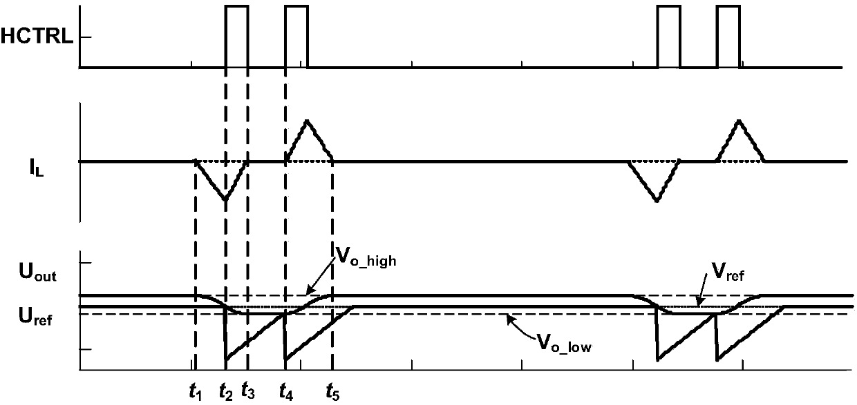
[0007] Depend on figure 2 It can be seen that in the super-audio mode of the existing switching power supply 100, the high-side control signal HCTRL may have two consecutive conduction pulses in the same cycle, so there will also be double pulses at the switching node SW, which makes the switching power supply output The voltage ripple is large, and the switching loss of the high-side switching tube HS is high, which adversely affects the efficiency of the switching power supply

Method used


Image

  • Switching power supply with constant on-time control, and control circuit and control method for switching power supply
  • Switching power supply with constant on-time control, and control circuit and control method for switching power supply
  • Switching power supply with constant on-time control, and control circuit and control method for switching power supply

Examples


Embodiment Construction

[0022] Specific embodiments of the present invention will be described in detail below, and it should be noted that the embodiments described here are only for illustration, not for limiting the present invention. In the following description, numerous specific details are set forth in order to provide a thorough understanding of the present invention. It will be apparent, however, to one of ordinary skill in the art that these specific details need not be employed to practice the present invention. In other instances, well-known circuits, materials or methods have not been described in detail in order to avoid obscuring the present invention.

[0023]Throughout this specification, reference to "one embodiment," "an embodiment," "an example," or "example" means that a particular feature, structure, or characteristic described in connection with the embodiment or example is included in the present invention. In at least one embodiment. Thus, appearances of the phrases "in one...


PUM


Abstract

The invention discloses a switching power supply with constant on-time control, and a control circuit and a control method for the switching power supply. When the switching power supply enters a superaudio mode, a low-side switch tube is switched on to discharge an output capacitor, a complementary ramp compensation signal of which the voltage is raised from initial voltage is generated in the discharge stage, the algebraic sum of the complementary ramp compensation signal and reference voltage is compared with a feedback signal representing output voltage, the discharge time of the low-side switch tube is shortened, the switch-on of a high-side switch tube is accelerated, audio noise is avoided, and dipulse in the superaudio mode is eliminated, so that the output voltage ripple of the switching power supply is reduced, the loss of the high-side switch tube is reduced, and the efficiency of the switching power supply is improved.

Description

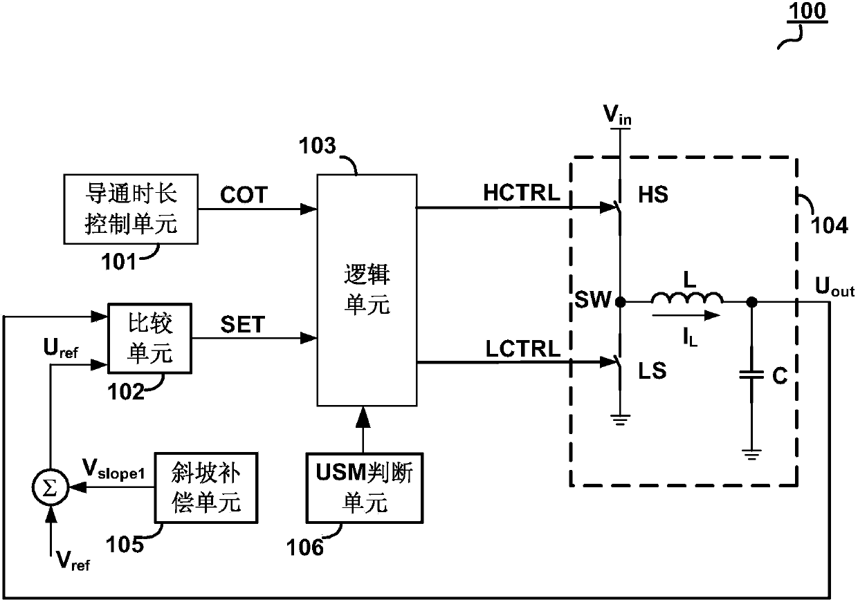
technical field [0001] Embodiments of the present invention relate to electronic circuits, and in particular to a switching power supply controlled by a constant on-time duration, a control circuit and a control method thereof. Background technique [0002] Constant on-time control has been well applied in the power supply field due to its superior load transient response, simple internal structure and smooth operation mode switching. figure 1 It is a schematic circuit diagram of a conventional switching power supply 100 controlled by a constant on-time duration. The switching power supply 100 includes a conduction duration control unit 101 , a comparison unit 102 , a logic unit 103 , a switch circuit 104 and a slope compensation unit 105 . The switch circuit 104 adopts a synchronous buck conversion topology, including a high-side switch HS, a low-side switch LS, an inductor L, and an output capacitor C, wherein the common terminal of the high-side switch HS and the low-sid...

Claims


Application Information

Patent Timeline
IPC IPC(8): H02M3/158
CPCH02M3/156H02M1/0032Y02B70/10H02M3/158
Inventor 姜礼节张加欣陆文斌胡望淼欧阳茜
Owner CHENGDU MONOLITHIC POWER SYST
Learn More