Transmitter gain distribution method and circuit

A distribution method and a technology of distribution circuits, which are applied in the direction of gain control, electrical components, and amplification control, etc., can solve problems such as poor carrier suppression ability, achieve the effects of reducing power consumption, improving efficiency, and meeting requirements

Active Publication Date: 2014-04-02
GUANGZHOU RUNXIN INFORMATION TECH +1
View PDF5 Cites 10 Cited by
  • Summary
  • Abstract
  • Description
  • Claims
  • Application Information

AI Technical Summary

Problems solved by technology

[0005] One of the purposes of the present invention is to propose a transmitter ga...

Method used


Image

  • Transmitter gain distribution method and circuit
  • Transmitter gain distribution method and circuit
  • Transmitter gain distribution method and circuit

Examples


Embodiment Construction

[0030] In the following, the present invention will be further described in conjunction with the drawings and specific embodiments.

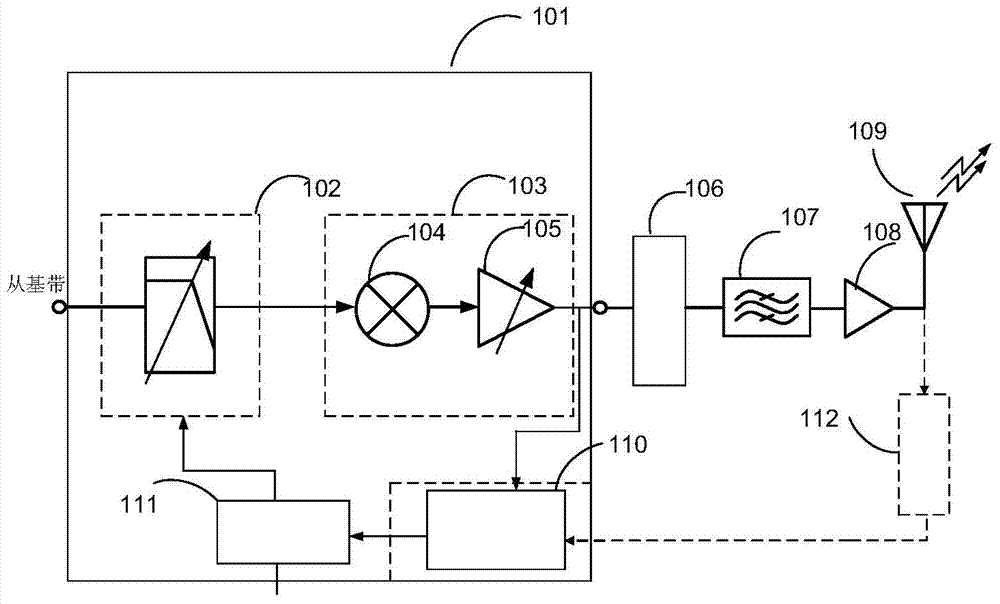
[0031] For the transmit link, the carrier leakage is mainly caused by the mismatch from the IF module, and the suppression of the carrier leakage is equivalent to the ratio of the useful signal to the mismatch product, that is, as far as possible when the mismatch product remains unchanged. Keeping the large signal output of the intermediate frequency can effectively suppress the carrier.

[0032] Based on the above ideas, combined with figure 2 Shown, a kind of transmitter gain distribution method, it comprises the following steps:

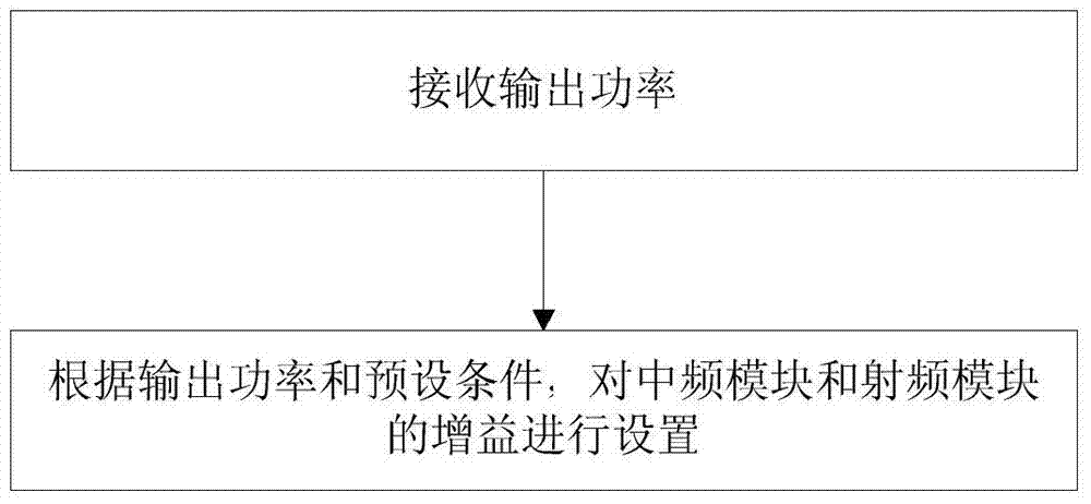
[0033] The output power of the receiving transmitter;

[0034] According to the output power of the transmitter and in combination with preset conditions, the gains of the intermediate frequency module and the radio frequency module of the transmitter chip of the transmitter are respectively set. Specifically, ...


PUM


Abstract

The invention relates to a transmitter gain distribution method and circuit. The method comprises the following steps: respectively setting a gain of an intermediate frequency module and a gain of a radio frequency module according to the output power of a transmitter and through combining a preset condition, wherein the preset condition is the corresponding relation among the output power, the gain of the intermediate frequency module and the gain of the radio frequency module; stepping the gain of the intermediate frequency module according to the step length of 1 dB, and circulating in the stepping range of 6 dB in sequence; stepping the gain of the radio frequency module according to the step length of 6 dB, wherein the stepping range is the dynamic range of the output power, and the value of the any gain of the radio frequency module corresponds to the values of six types of continuous output power, and corresponds to a circulation of the gain of the intermediate frequency module. According to the method and the circuit, the carrier leakage suppression can be optimized in the dynamic range of the overall output power effectively, and moreover, the power consumption is reduced along with the reduction of the output power, so that the efficiency is improved.

Description

technical field [0001] The invention relates to wireless communication technology, in particular to a transmitter gain distribution method and circuit. Background technique [0002] For modern wireless transceivers, its architecture depends on the innovation of communication system standards, the development of process technology and the improvement of circuit design technology. They promote each other and restrict each other. Based on the advantages of simple structure and easy integration, the CMOS direct up-conversion (zero-IF) transmission architecture has become the main choice for wireless communication satellite navigation transmitters, especially for Radio Determination Satellite Service Terminal (RDSS) transmitter systems. However, there is a serious problem in the prior art, which is its inherent local oscillator (carrier) leakage, which is mainly caused by the inherent DC offset and other mismatches in the circuit, and a large local oscillator leakage will affect...

Claims


Application Information

Patent Timeline
IPC IPC(8): H03G3/30
Inventor 何思远
Owner GUANGZHOU RUNXIN INFORMATION TECH
Why Eureka
Try Eureka