Flasher chip

A flasher and chip technology, applied in the field of flasher, can solve problems such as inconsistency of electrolytic capacitor capacitance, frequency change, difficult control by flasher manufacturers, etc., to avoid high current and high temperature burnout, save PCB area, reduce Capacitance effect

Active Publication Date: 2014-04-02
无锡迈尔斯通集成电路有限公司
View PDF10 Cites 5 Cited by
  • Summary
  • Abstract
  • Description
  • Claims
  • Application Information

AI Technical Summary

Problems solved by technology

During the chip test, the quiescent current of the chip can be adjusted to a certain accuracy, but the capacitance of the electrolytic capacitor itself is inconsistent, and it is difficult for the flasher manufacturer to control
Therefore, even if the accuracy of the quiescent current of the chip is adjusted to a high level, when the electrolytic capacitor changes, the frequency will also change.
Therefore, when using the ST1160 chip to design a flasher, it is difficult to guarantee the consistency of the flashing frequency

Method used


Image

  • Flasher chip
  • Flasher chip
  • Flasher chip

Examples


Embodiment Construction

[0018] The specific embodiments of the present invention will be further described below in conjunction with the accompanying drawings.

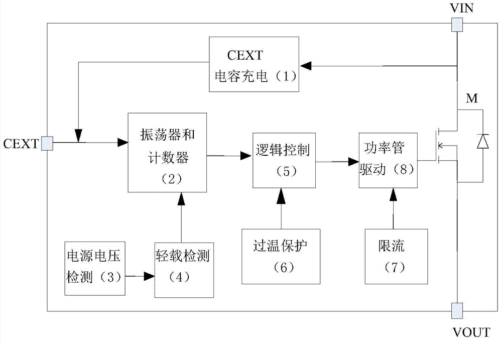
[0019] The internal block diagram of chip of the present invention is as figure 1 As shown, it consists of CEXT capacitor charging module 1, oscillator and counter module 2, power supply voltage detection circuit 3, light load detection circuit 4, logic control circuit 5, over-temperature protection circuit 6, current limiting circuit 7, power tube drive circuit 8 and power tube M. The chip has three pins of VIN, CEXT, and VOUT. CEXT is connected to the oscillator and counter module 2, and the oscillator and counter module 2 are sequentially connected to the logic control circuit 5 and the power tube drive circuit 8, and then connected to the gate of the power tube M; the drain of the power tube M is connected to VIN, and the source Connected to VOUT; CEXT capacitor charging module 1 is connected between VIN and CEXT; power supply voltage ...


PUM


Abstract

The invention discloses a flasher chip, which comprise a CEXT capacitor charging module, an oscillator, a counter module, a power voltage detection circuit, a light load detection circuit, a logical control circuit, an over-temperature protection circuit, a current limiting circuit, a power tube driving circuit and a power tube. The frequency of the flasher chip is controlled by an internal circuit and is irrelevant to an external capacitor; moreover, the control accuracy of the frequency is high, peripheral elements can be reduced, the area of a PCB (Printed Circuit Board) is small, and the functions of light load automatic detection, over-temperature protection and the like are realized.

Description

technical field [0001] The invention relates to a flasher used in electric vehicles and motorcycles, especially an integrated circuit chip of the flasher. Background technique [0002] Flashers are essential in electric vehicles and motorcycles. When electric vehicles and motorcycles are turning or temporarily parking, they need to turn on the flasher to remind driving and passers-by. [0003] At present, most of the flash circuits on the market are composed of discrete devices. Such flashers are expensive, have a large PCB area, and have poor consistency of flashing frequency, and do not have functions such as over-temperature protection and light-load detection. There are also chips developed abroad, such as the ST1170 chip of Ruyi Semiconductor, but the quiescent current of this chip is about 700uA, so a 220uF electrolytic capacitor is needed to power the internal control circuit of the chip. However, the volume of the electrolytic capacitor itself is large, so that the...

Claims


Application Information

Patent Timeline
Patent Type & Authority Applications(China)
IPC IPC(8): H05B37/02
Inventor 陈俊杨烨照谢凌寒麻坚江谭海峰
Owner 无锡迈尔斯通集成电路有限公司
Why Eureka
Try Eureka