Eureka AIR delivers breakthrough ideas for toughest innovation challenges, trusted by R&D personnel around the world.

Transverse flow marine turbine with autonomous stages

A technology of turbine engine and turbine, which is applied in the direction of reaction engine, wind turbine and engine at right angles to the wind direction, and can solve problems such as inability to provide efficiency

Inactive Publication Date: 2014-04-02
ELECTRICITE DE FRANCE +1
View PDF7 Cites 0 Cited by
  • Summary
  • Abstract
  • Description
  • Claims
  • Application Information

AI Technical Summary

Problems solved by technology

[0012] All of these turbine engines suffer from one or another of several disadvantages and do not provide optimum efficiency

Method used


Image

  • Transverse flow marine turbine with autonomous stages
  • Transverse flow marine turbine with autonomous stages
  • Transverse flow marine turbine with autonomous stages

Examples


Embodiment Construction

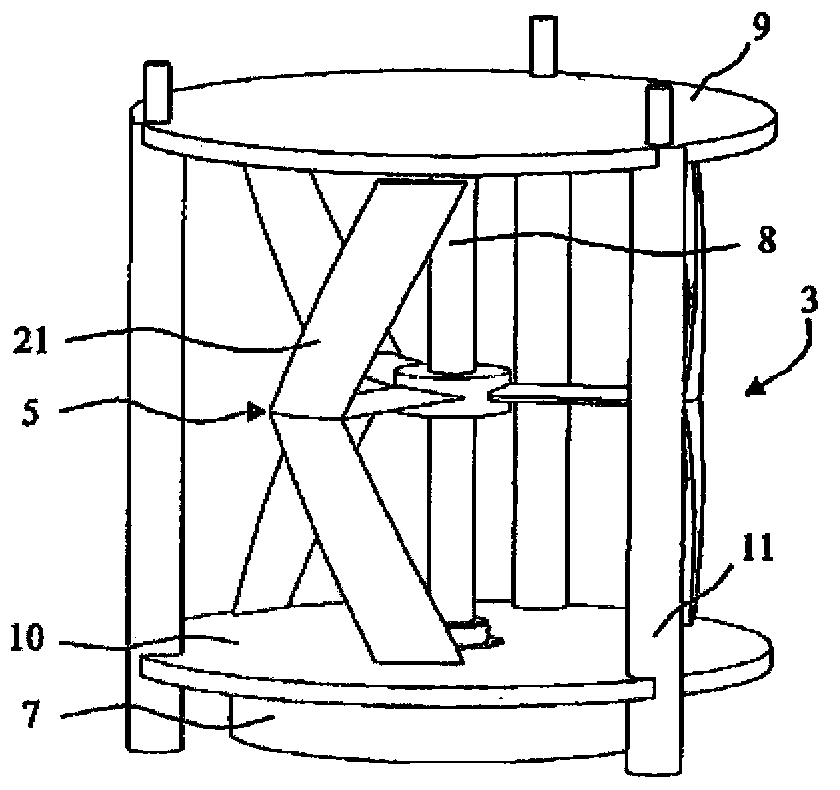
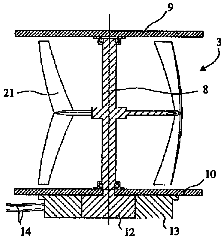
[0040] Figure 1A , Figure 1B and Figure 1C are simplified diagrams showing a single-row cross-flow water turbine engine, a perspective view of a stage of the turbine engine, and a partial cutaway view of a stage of the turbine engine, respectively. These views are simplified in particular in that they do not show components for attaching or connecting the turbine engine. The turbine engine 1 consists of a set of stages 3 , each stage comprising a cross-flow turbine 5 and a generator 7 . For example, each basic turbine is of the type described in patent application 04 / 50209 (B6412) and is firmly attached to a shaft 8 which is rotatably fitted between an upper flange 9 and a lower flange 10, the upper The flange 9 and the lower flange 10 are connected by a rod 11 . The shafts of the individual turbine-generator stages are independent of each other. Each shaft 8 drives a rotor 12 of a generator 7 , which rotates inside a stator 13 , which provides an electrical supply via ...


PUM


Abstract

The invention relates to a turbomachine comprising a stack of stages each of which comprises a transverse-flow turbine and a generator, in which machine each turbine-generator stage has an independent shaft, and in which each stage is associated with an independent fairing (31-32) that orients it with respect to a current, each fairing being of the diffuser type, with symmetric profiled vanes.

Description

technical field [0001] The invention relates to a cross-flow water turbine engine composed of at least one row of stacked turbines. Background technique [0002] The inventors have filed a set of applications for cross-flow hydro turbine engines in which: [0003] - French patent application 04 / 50209 (B6412) filed on February 4, 2004, which relates to a cross-flow hydraulic turbine engine comprising a row of turbines, each turbine comprising blades in the form of V-shaped airfoils; [0004] - French patent application 05 / 50420 (B6869) filed on February 14, 2005, concerning a support structure for stabilizing and avoiding deformation of a turbine train; and [0005] - Patent application PCT / FR2008 / 051917 (B8450) filed on October 23, 2008, which relates to a turbine engine consisting of two double-row assemblies rotating in opposite directions. [0006] These patent applications, which are hereby considered known, describe turbine engines consisting of at least one row of st...

Claims


Application Information

Patent Timeline
Patent Type & Authority Applications(China)
IPC IPC(8): F03B13/10F03B13/26F03B17/06
CPCF05B2240/133Y02E10/28F03B13/10F04D13/00F03B17/063F03B13/264F05B2240/40F05B2240/13Y02E10/74F03D3/02Y02E10/30F03B13/26F03B17/06F03B3/12Y02E10/20
Inventor 托马斯·雅基耶让-吕克·阿夏德
Owner ELECTRICITE DE FRANCE
Why Eureka
Eureka Blog
Learn More