Video data generation unit, video image display device, video data generation method, video image display method, and video image file data structure

A technology of data generation and generation unit, applied in the direction of image communication, electrical components, video games, etc., to achieve the effect of smooth responsiveness

Active Publication Date: 2014-04-02
SONY COMPUTER ENTERTAINMENT INC
11 Cites 5 Cited by

AI-Extracted Technical Summary

Problems solved by technology

[0003] Improving the efficiency with which images are displayed, whethe...

Method used

Therefore, as shown in Figure 9, the switching frequency of the grouping 180a of the first layer Lv1 and the second layer Lv2 is the highest, followed by the grouping 180b of the third layer Lv3 and the fourth layer Lv4, Then the packet 180c of the fifth layer Lv5 and the sixth layer Lv6 follows, that is, the switching frequency of the packets of the lower layer becomes lower. By continuously setting the corresponding switching time points while taking into account the characteristics of the corresponding layers, the necessary bandwidth can be reduced more effectively in a principle similar to that explained with FIG. 8 .
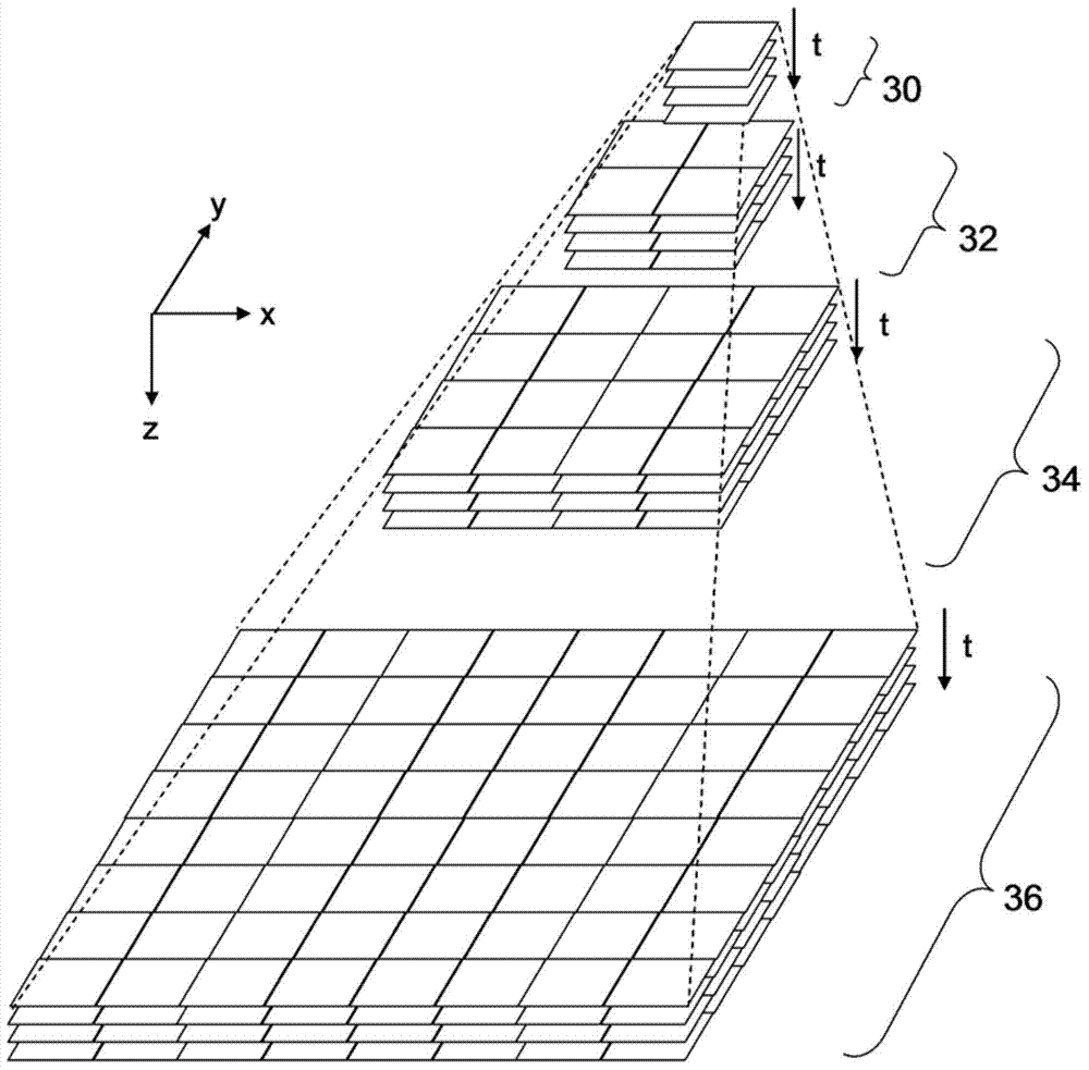
[0037] Therefore, according to the present embodiment, data of a moving image to be displayed is configured in a hierarchical structure in which frames of a moving image are expressed with a plurality of resolutions and arranged in layers in order of resolution. Furthermore, a moving image stream is formed for each block obtained by spatially dividing a frame in each of the layers. Good responsiveness is obtained by switching a layer to be used for display to another layer and a moving image stream to be used for display to another moving image stream in accordance with the movement of the display area. Hereinafter, moving image data having such a hierarchical structure is also referred to as "hierarchical data".
[0063] The same applies to the image prefetching process in the upward, downward, leftward or rightward direction. More specifically, a prefetch boundary is set in advance in the image data developed in the buffer memory 70 so that when the display position indicated by the signal requesting movement of the display area exceeds the prefetch boundary, the prefetch process is started. Thereby, it is possible to realize a mode in which moving image reproduction is performed while smoothly changing the resolution and the display position according to a request from the user to move the display area.
[0072] In an embodiment in which movement of the display area including zooming in/out is allowed while playing back a moving image, it is desirable that all moving image streams share a common time axis and that no matter which moving image stream is to be used Frames are rendered seamlessly whether switched to another stream or not. Therefore, as described above, a moving image stream for displaying an area required at a certain time and/or expected thereafter is loaded and decoded with high priority in order to improve the processing efficiency required for frame rendering. In addition, as will be described later, by appropriately configuring the moving image stream, whenever the moving image stream to be used for display is switched to another stream, frames start to be displayed with low delay.
[0079] Therefore, by switching from allocating an original image layer and a dif...

Abstract

An objective of the invention is to make a video image frame into a hierarchical structure represented with a plurality of resolutions. With a zeroth layer (30), a first layer (32), a second layer (34), and a third layer (36) in order by increasing resolution, layer data which denotes a frame at a time (t1) treats the zeroth layer (30) and the second layer (34) as base image layers, and the first layer (32) and third layer (36) as difference image layers. In such a circumstance, when a region (124a) is displayed with the resolution of the third layer (36), an image of a corresponding region (126a) which the second layer (34) retains is enlarged to the resolution of the third layer (36) and each pixel value added to a difference image of a region (124a) which the third layer (36) retains. The layer which is treated as the difference image layer is switched with the passage of time (t2, t3, ...).

Application Domain

Television system detailsElectronic editing digitised analogue information signals +7

Technology Topic

Image resolutionImage layer +5

Image

  • Video data generation unit, video image display device, video data generation method, video image display method, and video image file data structure
  • Video data generation unit, video image display device, video data generation method, video image display method, and video image file data structure
  • Video data generation unit, video image display device, video data generation method, video image display method, and video image file data structure

Examples

  • Experimental program(1)

Example Embodiment

[0036] According to this embodiment, when a moving image is displayed, the display area can be moved in response to a request from the user to move the viewpoint. Moving the viewpoint includes moving the viewpoint closer to or away from the image plane when playing back a moving image, and correspondingly enlarge or reduce the moving image. In such an embodiment, the wider the variable range of the resolution is expanded, and the larger the size of the image becomes, the more difficult it is to respond to the user's operation input and display the movement of the requested area with smooth and good responsiveness. image.
[0037] Therefore, according to the present embodiment, the data of the moving image to be displayed is configured in a layered structure in which frames of the moving image are expressed with a plurality of resolutions and are arranged in layers in the order of resolution. In addition, a moving image stream is formed for each block obtained by spatially dividing the frame in each of the layers. Good responsiveness is obtained by switching the layer to be used for display to another layer and switching the moving image stream to be used for display to another moving image stream in accordance with the movement of the display area. Hereinafter, moving image data having such a hierarchical structure is also referred to as “hierarchical data”.
[0038] First, an explanation of the basic mode for displaying such hierarchical data is given. figure 1 An environment is shown in which the image processing system 1 to which the embodiment can be applied is used. The image processing system 1 includes an image processing device 10 for executing image processing software and a display device 12 that outputs a processing result of the image processing device 10. The display device 12 may be a television equipped with a display for outputting images and a speaker for outputting sound.
[0039] The display device 12 may be connected to the image processing device 10 via a cable or wirelessly via a wireless local area network (LAN) or the like. The image processing device 10 in the image processing system 1 may be connected to an external network such as the Internet through a cable 14 to download and acquire moving image data. The image processing apparatus 10 can be connected to an external network via wireless communication.
[0040] For example, the image processing device 10 may be a game device or a personal computer, and the image processing function may be realized by loading an application program for image processing. The image processing device 10 enlarges/reduces the moving image displayed on the display of the display device 12 or scrolls the moving image up, down, left, or right in accordance with a request from the user to move the viewpoint. Hereinafter, this change of the display area including enlargement/reduction is referred to as "movement of the display area". When the user operates the input device while viewing the image displayed on the display, the input device sends a signal requesting movement of the display area to the image processing device 10.
[0041] figure 2 An example of the external configuration of the input device 20 is shown. The input device 20 is equipped with direction keys 21, analog joysticks 27a and 27b, and four types of control buttons 26 as operation means that can be manipulated by the user. The four types of control buttons 26 include round buttons 22, cross buttons 23, square buttons 24, and triangle buttons 25.
[0042] The operating means of the input device 20 in the image processing system 1 is assigned a function of inputting a request for zooming in/out a displayed image and a function of inputting a request for scrolling up, down, left, or right. For example, a function of inputting a request for zooming in/out a display image is assigned to the right analog joystick 27b. The user may input a request for zooming in the displayed image by pulling the analog joystick 27b toward the user, and may input a request for zooming in the displayed image by pushing the analog joystick 27b away from the user.
[0043] The function of inputting a request for scrolling is assigned to the direction key 21. By pressing the direction key 21, the user can input a request to scroll in the direction in which the direction key 21 is pressed. The function of inputting a request for moving the display area may be assigned to an alternative operation means. For example, a function of inputting a request for scrolling may be assigned to the analog joystick 27a.
[0044] The input device 20 has a function of sending a signal requesting movement of the input display area to the image processing device 10. In this embodiment, the input device 20 is configured so that the input device 20 can communicate with the image processing device 10 wirelessly. The input device 20 and the image processing device 10 may establish a wireless connection using Bluetooth (registered trademark) protocol, IEEE802.11 protocol, or the like. The input device 20 may be connected to the image processing device 10 via a cable to send a signal requesting movement of the display area to the image processing device 10.
[0045] The input device 20 is not limited to figure 2 The equipment shown. The input device 20 may be a keyboard, a touch panel, buttons, etc. operated by a user, a camera that captures an image of a target object, a microphone that captures sound, etc., and may be an interface of any type and/or appearance, as long as the interface can capture the user's The intention, the movement of the target object, etc. are used as electronic information.
[0046] image 3 The hierarchical data of the moving image to be processed in this embodiment is conceptually shown. The layered data has a layered structure including the 0th layer 30, the first layer 32, the second layer 34, and the third layer 36 in the z-axis direction, that is, from the top to the bottom of the figure. . Although the figure shows only four strata, the number of strata is non-limiting. As described above, each layer includes moving image data of a single moving image expressed with different resolutions, that is, data of a plurality of image frames arranged in chronological order. In this figure, each layer is symbolically represented by four image frames. The number of image frames obviously varies depending on the playback time and frame rate of the moving image.
[0047] The hierarchical data has, for example, a quad-tree hierarchical structure; when the image frames constituting the hierarchical layer are divided into "tile images" of the same size, a parallel display is included in the 0th layer 30 For images, the first layer 32 includes 2×2 side-by-side display images, the second layer 34 includes 4×4 side-by-side display images, the third layer includes 8×8 side-by-side display images, and so on. In this case, the resolution of the Nth layer (N is an integer equal to or greater than 0) in both the horizontal (X axis) direction and the vertical (Y axis) direction on the image plane is the (N+1)th 1/2 of the resolution of the layer. For example, hierarchical data can be generated by reducing image frames in a plurality of hierarchies based on a moving image in the third hierarchical 36 having the highest resolution.
[0048] Such as image 3 As shown, when the moving image is displayed, the coordinates of the viewpoint and the coordinates of the corresponding display area can be in a virtual three-dimensional form formed by the x-axis representing the horizontal direction of the image, the y-axis representing the vertical direction of the image, and the z-axis representing the resolution. In space. As described above, in this embodiment, the moving image data in which a plurality of image frames are sequentially arranged is arranged as one layer. Therefore, the actually displayed image also depends on the amount of time taken from the start of reproduction. Therefore, the time axis t is also shown for each layer in the figure.
[0049] The image processing device 10 basically continuously presents image frames of any one of the layers along the time axis t at a predetermined frame rate. For example, the image processing device 10 displays a moving image of the resolution of the 0th layer 30 as a reference image. If a signal requesting movement of the display area is provided from the input device 20 during this process, the image processing device 10 derives the amount of change in the displayed image from the signal and uses the amount of change to derive the value of subsequent frames (frame coordinates) in the virtual space. The coordinates of the four corners. The image processing device 10 then presents an image frame corresponding to the frame coordinates. In this case, by providing switching boundaries for each layer with respect to the z axis, the image processing device 10 appropriately switches the layering of moving image data for frame presentation in accordance with the value of z of the frame coordinates.
[0050] Instead of the frame coordinates in the virtual space, the image processing device 10 may derive both the information identifying the layer and the texture coordinates (UV coordinates) in the layer. Hereinafter, the combination of the information identifying the layer and the texture coordinates are also referred to as frame coordinates.
[0051] The hierarchical data is compressed for each side-by-side display image, and the hierarchical data is stored in the memory of the image processing apparatus 10. Then, the data required for frame presentation is read from the memory device and decoded. image 3 The hierarchical data is conceptually shown, and the storage order or format of the data stored in the memory device is not limited. For example, as long as the position of the hierarchical data in the virtual space is mapped to the actual storage area of ​​the moving image data, the moving image data can be stored in any area.
[0052] Figure 4 The configuration of the image processing apparatus 10 is shown. The image processing apparatus 10 includes an air interface 40, a switch 42, a display processing unit 44, a hard disk drive 50, a recording medium loading unit 52, a magnetic disk drive 54, a main memory 60, a buffer memory 70, and a control unit 100. The display processing unit 44 is equipped with a frame memory for buffering data to be displayed on the display of the display device 12.
[0053] The switch 42 is an Ethernet switch (Ethernet is a registered trademark) and is a device connected to an external device via a cable or wirelessly in order to send and receive data. The switch 42 is connected to an external network via the cable 14 to receive hierarchical data from the image server. The switch 42 is connected to the air interface 40. The air interface 40 is connected to the input device 20 using a predefined wireless communication protocol. A signal requesting movement of the display area as a user's input via the input device 20 is provided to the control unit 100 via the air interface 40 and the switch 42.
[0054] The hard disk drive 50 is used as a storage device for storing data. Moving image data may be stored in the hard disk drive 50. If a removable recording medium such as a memory card is installed, the recording medium loading unit 52 reads data from the removable recording medium. When a read-only ROM disk is installed, the disk drive 54 drives and recognizes the ROM disk in order to read data. The ROM disc can be an optical disc, a magneto-optical disc, and the like. Moving image data can be stored in a recording medium.
[0055] The control unit 100 is equipped with a multi-core CPU. A single CPU is provided with a general-purpose processor core and multiple simple processor cores. The general-purpose processor core is called the power processor unit (PPU), and the other processor cores are called the co-processor unit (SPU). The control unit 100 may be further equipped with a graphics processing unit (GPU).
[0056] The control unit 100 is equipped with a memory controller connected to the main memory 60 and the buffer memory 70. The PPU is equipped with registers and a main processor as an entity that performs calculations. The PPU efficiently allocates tasks to the corresponding SPU as the basic unit of processing in the application. The PPU itself can perform tasks. The SPU is equipped with registers, a sub-processor as an entity that performs calculations, and a local memory as a local storage area. A local memory can be used as the buffer memory 70.
[0057] The main memory 60 and the buffer memory 70 are storage devices, and are formed as random access memories (RAM). The SPU is equipped with a dedicated direct memory access (DMA) controller and can perform high-speed data transfer between the main memory 60 and the buffer memory 70. High-speed data transmission can also be realized between the frame memory of the display processing unit 44 and the buffer memory 70. The control unit 100 according to this embodiment implements high-speed image processing by operating multiple SPUs in parallel. The display processing unit 44 is connected to the display device 12, and outputs an image processing result according to a user request.
[0058] The image processing apparatus 10 sequentially loads moving image data closely related to the frame currently being displayed in space and time from the hard disk drive 50 into the main memory 60 in advance to smoothly perform zooming in/out or scrolling of the displayed image. In addition, the image processing apparatus 10 decodes a part of the moving image data loaded in the main memory 60 and stores the decoded data in the buffer memory 70 in advance. Thereby, the display area can be moved smoothly while allowing playback of moving images. In this case, the data to be loaded or decoded can be determined by predicting the area that will become necessary later based on the early direction of the movement of the display area.
[0059] in image 3 In the hierarchical data shown, the position in the Z-axis direction indicates the resolution. The closer to the 0th layer 30, the lower the resolution. The closer to the third layer 36, the higher the resolution. In terms of the size of the image displayed on the display, the position in the z-axis direction represents the scale. Assume that the zoom factor of the image displayed in the third layer 36 is 1, the zoom factor in the second layer 34 is 1/4, the zoom factor in the first layer 32 is 1/16, and the The scaling factor in the 0th layer 30 is 1/64.
[0060] Therefore, if the display image changes away from the 0th layer 30 toward the third layer 36 in the z-axis direction, the displayed image is enlarged. If the display image changes in this direction away from the third layer 36 toward the 0th layer 30, the displayed image is reduced. For example, when the zoom factor of the display image is close to the zoom factor of the second layer 34, the display image is generated by using the image data on the second layer 34.
[0061] More specifically, as described above, the switching limit is provided to, for example, the corresponding intermediate scaling factor of each layer. For example, if the zoom factor of the image to be displayed is between the switching boundary between the first layer 32 and the second layer 34 and the switching boundary between the second layer 34 and the third layer 36, use the second layer 34 on the image data to present the frame. In this case, when the zoom factor is between the second layer 34 and the switching boundary between the first layer 32 and the second layer 34, the image frame of the second layer 34 is reduced for display . When the zoom factor is between the second layer 34 and the switching boundary between the second layer 34 and the third layer 36, the image frame of the second layer 34 is enlarged for display.
[0062] At the same time, when identifying and decoding the area predicted by the signal requesting to move the display area that will become necessary in the future, the scaling factor of each layer or the like is set in advance as a prefetch boundary. For example, when the reduction ratio requested by the signal requesting to move the display area exceeds the zoom factor of the second layer 34, the image processing apparatus 10 prefetches the first layer 32 located in the reduction direction from the hard disk drive 50 or the main memory 60 At least a part of the image data of, decode the prefetched image data, and write the decoded image data into the buffer memory 70.
[0063] The same applies to the image prefetching process in up, down, left, or right directions. More specifically, the prefetch boundary is set in the image data developed in the buffer memory 70 in advance, so that when the display position indicated by the signal requesting to move the display area exceeds the prefetch boundary, the prefetch process is started. Thereby, it is possible to realize a mode in which moving image reproduction is performed while smoothly changing the resolution and the display position in accordance with a request from the user to move the display area.
[0064] Figure 5 The configuration of the control unit 100a having a function of displaying moving images using moving image data having a layered structure in the present embodiment is shown in detail. The control unit 100a includes: an input information acquisition unit 102 for acquiring information input by the user via the input device 20; a frame coordinate determination unit 110 for determining the frame coordinates of the latest area to be displayed; and a loading area determination unit 106 for using For determining the latest compressed data to be loaded on the moving image stream; and the loading unit 108 for loading the necessary moving image stream from the hard disk drive 50. The control unit 100a further includes a decoding unit 112 for decoding compressed data on the moving image stream and a display image processing unit 114 for rendering image frames.
[0065] in Figure 5 And later Figure 15 , The elements in the functional blocks that instruct various processes are implemented in hardware through any central processing unit (CPU), memory or other LSI, and implemented in software through programs loaded in memory or the like. As described above, the control unit 100 has one PPU and multiple SPUs, and may only be composed of one PPU, one SPU, or a combination of the two to form a functional block. Therefore, it is obvious to those skilled in the art that the functional blocks can be implemented in various ways through a combination of hardware and software. Therefore, it is obvious to those skilled in the art that the functional blocks can be implemented in various ways of only hardware, only software, or a combination thereof.
[0066] The input information acquiring unit 102 acquires a request input by the user via the input device 20 to start/terminate moving image reproduction, moving a display area, etc., and notifies the frame coordinate determination unit 110 of the request. The frame coordinate determining unit 110 determines the frame coordinates of the latest area to be displayed according to the frame coordinates of the current display area and the signal requesting movement of the display area input by the user, and notifies the loading area determining unit 106 of the determined frame coordinates to the decoding The unit 112 and the display image processing unit 114.
[0067] Based on the frame coordinates notified by the frame coordinate determining unit 110, the loading area determining unit 106 specifies the moving image data to be newly loaded from the hard disk drive 50 and issues a loading request to the loading unit 108. As described above, according to the present embodiment, each hierarchical series of frames forms one or more independent moving image streams for each side-by-side display image. Therefore, basically, a moving image stream whose number is the number of side-by-side display images per layer is formed. Alternatively, data indicating the same area of ​​multiple hierarchical or multiple side-by-side displayed images may coexist in one moving image stream, which will be described later.
[0068] Information that associates the identification number indicating the position of the layered and side-by-side display image and the identification number of the moving image stream data itself is attached to the moving image data in advance, and the information is loaded into the main memory when the moving image is started to be played back 60 in. Based on the frame coordinates, the loading area determination unit 106 refers to the information and obtains the identification number of the moving image stream of the necessary area. If the data of the corresponding moving image stream has not been loaded, the loading area determining unit 106 issues a loading request to the loading unit 108. Even if the frame coordinates do not change, the loading area determination unit 106 sequentially requests the loading of necessary moving image stream data in accordance with the progress of the moving image. The moving image stream can be divided into sub-streams in time in advance, and can be loaded on the sub-streams on a sub-stream basis.
[0069] In addition to the moving image stream necessary for presenting the frame at this moment, the loading area determination unit 106 may specify the moving image stream expected to be required later by the prefetching process described earlier, etc., and issue a loading request to the loading unit 108. In accordance with the request issued by the loading area determination unit 106, the loading unit 108 executes the loading process of the moving image stream from the hard disk drive 50. More specifically, the loading unit 108 recognizes the storage area in the hard disk drive 50 from the identification number of the moving image stream to be loaded, and stores the data read from the storage area in the main memory 60.
[0070] Based on the frame coordinates at each time point, the decoding unit 112 reads the necessary moving image stream data from the main memory 60, decodes the read data, and sequentially stores the decoded data in the buffer memory 70 in. The decoding target may be in the unit of the moving image stream. When the area defined by the frame coordinates determined by the frame coordinate determining unit 110 is located across multiple moving image streams, the decoding unit 112 decodes the multiple moving image streams.
[0071] According to this embodiment, the data size of the hierarchical data is reduced by retaining one or more hierarchical data of the hierarchical data as a differential image, the differential image representing a part of the image and the layered data above the part. The difference value between the magnified images of the image on the layer, which will be described later. Therefore, if the decoded image is a differential image, the decoding unit 112 further decodes the image on the higher layer used when generating the differential image, enlarges the image on the higher layer, and removes the image on the higher layer. The image is added to the decoded differential image, thereby restoring the original image data and storing the original image data in the buffer memory 70. Based on the frame coordinates at each time point, the display image processing unit 114 reads out the corresponding data from the buffer memory 70 and presents the data in the frame memory of the display processing unit 44.
[0072] In one embodiment, in which movement of the display area including zoom in/out is allowed while playing back a moving image, it is ideal that all moving image streams share a common time axis, and whether the moving image stream to be used is switched or not Frame rendering is performed seamlessly to another stream. Therefore, as described above, an area required for display at a certain time and/or a moving image stream expected to be required thereafter is loaded and decoded with high priority in order to improve processing efficiency required for frame presentation. In addition, as will be described later, by appropriately configuring the moving image stream, whenever the moving image stream to be used for display is switched to another stream, the frame starts to be displayed with low delay.
[0073] With the above configuration, even for a large-size moving image, for example, one frame of which is a moving image of the gigapixel level, it is possible to freely and smoothly ignore the entire image, enlarge a part of the image, and so on. In addition, by arranging moving images in a layered structure, it is possible to display moving images regardless of the similar appearance of the display device by selecting an appropriate layer according to the resolution and/or the size of the display, the processing capability of the device, and the like.
[0074] For images at the same time point of different layers included in the layered data of the moving image, although their resolutions are different, their contents are the same. Therefore, hierarchical data is always born with redundancy between layers. Therefore, according to the present embodiment, as described above, one or more layers of layered data are configured as a difference image between the layer and the enlarged image of the image on the layer higher than the layer. Considering the nature of the above-mentioned hierarchical data, its data size can be significantly reduced by using the difference between hierarchies.
[0075] Image 6 It schematically shows the state of some layers of moving image data having a layered structure represented by the difference image. In the example shown in the figure, the 0th layer 30 and the second layer 34 retain the original image data, and the first layer 32 and the third layer 36 retain the data of the differential image. The original data is shown by the outline of the white part, and the difference image data is shown by the shaded part. In the following description, the layer that retains the original image data is called "original image layering", and the layer that retains the data of the differential image is called "differential image layering".
[0076] In the case where the area 120 to be displayed has the resolution of the third layer 36, the image of the corresponding area 122 reserved by the second layer 34 after being enlarged to the resolution of the third layer 36 is pixel by pixel. It is added to the difference image of the area 120 reserved by the third layer 30. In the case shown in the figure, since the resolution of the third layer 36 is 2×2 times the resolution of the second layer 34, the image of the area 122 is enlarged to 2×2 times. For amplification, common interpolation methods such as nearest neighbor method, bilinear method, bicubic method, etc. can be used.
[0077] By configuring the data in this way, the total data size can be reduced. In addition, it is possible to limit the necessary bandwidth of the transmission path through which the data passes when the data is displayed (ie, the internal bus in the image processing apparatus 10, the network connected to the image server, etc.). This is because, compared with the data size of the original image at the ideal resolution at which the original image is to be displayed, the data of the differential image at the ideal resolution and the original The data size of the sum of the image data is smaller.
[0078] in Image 6 In the example shown, the allocation of the original image layer and the differential image layer is fixed. In this case, the bit rate when displaying the image with the resolution of the differential image layering is low. Therefore, the bandwidth required to transmit data can be reduced. At the same time, in the period of displaying the image with the resolution of the original image layering, the bit rate is the same as the bit rate in the case where the differential image layering is not provided. Therefore, the bandwidth reduction effect cannot be obtained. In order to display images smoothly and uninterrupted at any resolution in any layer, a bandwidth that meets the maximum bit rate needs to be reserved. Therefore, this embodiment hardly leads to a reduction in reserved bandwidth.
[0079] Therefore, by switching from the allocation of an original image layer and a differential image layer to another allocation mode according to a predetermined rule, the bit rate is averaged, and the transmission data size is limited for a period longer than the switching period, and can be Reduce the bandwidth required for transmission. Figure 7 A diagram for illustrating an embodiment of switching the allocation of the original image layer and the differential image layer between some allocation modes is shown. In the figure, the horizontal axis indicates the time axis of the moving image. The figure only shows the configuration that only contains the hierarchical data of the corresponding frames at the time points t1, t2, and t3, respectively.
[0080] First, in the layered data representing the frame at time t1, the 0th layer 30 and the second layer 34 are set as the original image layer, and the first layer 32 and the third layer 36 are set as the differential image layer. Floor. In this case, an image with the resolution of the first layer 32 can be obtained by calculating the addition of the difference image of the first layer 32 and the original image of the 0th layer 30. The image with the resolution of the third layer 36 can be obtained by calculating the addition of the difference image of the third layer 36 and the original image of the second layer 34.
[0081] In the layered data representing the frame at time t2 later than time t1, the 0th layer 30, the first layer 32, and the third layer 36 are set as the original image layer, and the second layer 34 is set as Poor image layering. In this case, an image with the resolution of the second layer 34 can be obtained by calculating the addition of the difference image of the second layer 34 and the original image of the first layer 32. For the hierarchical data representing the frame at the later time t3, the allocation is the same as the allocation pattern at the time t1.
[0082] For example, in the case where the area 124a is to be displayed at the resolution of the third layer 36 in the frame at time t1, the data of the difference image of the area 124a and the data of the corresponding area 126a included in the original image of the second layer 34 are required. Image data. Assume that the display area moves with the progress of the frame as time passes, and the area 124b is to be displayed at the resolution of the third layer 36 in the frame at time t2. In this case, since the third layer 36 is the data of the original image, only the data of the area 124b is needed. As time progresses further, in the case where the area 124c is to be displayed at the resolution of the third layer 36 in the frame at time t3, the data of the differential image of the area 124c and the original image included in the second layer 34 are required Image data of the corresponding area 126c in.
[0083] Therefore, as shown at the bottom of the figure, in order to display the area 124a, the area 124b, and the area 124c at the resolution of the third layer 36 in the frame at time t1, t2, and t3, respectively, data 128a, data 128b, and 128c are sequentially read. The data 128a is a collection of the difference image of the third layer 36 and the original image of the second layer 34. The data 128b is the data of the original image of the third layer 36. The data 128c is a collection of the difference image of the third layer 36 and the original image of the second layer 34.
[0084] In this manner, switching the configuration of the original image layering and the differential image layering in time reduces the possibility of continuously transmitting large-size data such as the original image data 128b. Therefore, the data size (ie, bit rate) to be transmitted per unit time can be reduced. For ease of understanding, the target to be displayed is fixed at the resolution of the third layer 36 in the figure. However, even if the target layer for display is changed to another layer in the middle, a similar effect can be obtained.
[0085] Figure 8 to 11 Shows an example of the schedule used to allocate the original image layer and the difference image layer. In these figures, the horizontal axis represents the elapsed time, and the white rectangle represents the original image layering period, and the shaded rectangle represents the differential image layering period, where the 0 Layers, the first layer, the second layer...represented by "Lv0", "Lv1", "Lv2"... In a period represented by a rectangle, one or more frames are displayed.
[0086] Figure 8 Shows a situation where the time point for switching allocation is shared across the entire hierarchical data. The 0th layer is always set as the original image layer 152 because no layer is stored on the 0th layer. The same applies to the following example. in Figure 8 In the example shown, the allocation of each layer is switched at one or more layers at time points T0, T1, T2, T3, T4, T5, and T6. For example, in the period from the time point T0 to T1, the 0th layer Lv0 and the second layer Lv2 are set as the original image layers 152 and 156, the first layer Lv1, the third layer Lv3 and the fourth layer The layer Lv4 is set as the differential image layer 154, 160, and 162, wherein the second layer Lv2 is switched to the differential image layer 164 at the time T1, and the third layer Lv3 is switched to the original image layer 166.
[0087] At time T2, the first layer Lv1 and the fourth layer Lv4 are switched to the original image layer 168 and 170, respectively, and the third layer Lv3 is switched to the difference image layer 172. At time T3, the first layer Lv1 and the fourth layer Lv4 are switched to the difference images 174 and 176, respectively, and the second layer Lv2 is switched to the original image layer 178. This switching is repeated thereafter. Then, except for the 0th layer Lv0, the original image layer is switched from the first layer Lv1 to —> The second layer Lv2—> The third layer Lv3—> In the fourth layer Lv4, the layers other than the original image layer are set as the differential image layer.
[0088] in Figure 8 In the illustrated embodiment, the number and arrangement of layers that are simultaneously set as the original image layer, and the number and arrangement of layers that are simultaneously set as the difference image are not limited to those shown in the figure, Rather, any number and arrangement may be adopted as long as the combination of the layer set as the original image layer and the layer set as the differential image layer is changed at a point in time common to all layers. in Figure 8 In the example shown, the differential image layering is set as vertical continuous layering in any period. For example, in the period from time T2 to time T3, the second layer Lv2 and the third layer Lv3 that are continuous in the vertical direction are set as the differential image layers 179 and 172.
[0089] In the case of such an allocation, in which more than one continuous layer is set as a differential image layer at the same time, the differential image can be generated by subtracting from the layer directly above, or it can be generated by searching the original image and extracting from the original image Subtract to generate. In the former case, the difference image obtained from the difference image is retained, unless the layer directly above is the original image layer. Therefore, the lower the layer position relative to the original image layer, the greater the number of layers and the more addition processing to restore the image. However, the data size becomes smaller.
[0090] In the latter case, the number of layers and the amount of addition processing required to restore the image remain unchanged. However, the lower the layer position relative to the original image layer, the greater the difference. Therefore, the data size is larger than that in the former case. Consider the content of the moving image, the processing capacity of the display device, the available transmission frequency band, etc. to determine which differential image to use. Alternatively, the schedule may be determined so that the differential image layer is not assigned to the continuous layer.
[0091] The switching time point T0-T6 can be set at a fixed time interval. In this case, switching is made for each predetermined number of frames (for example, for every eight frames) at least at one of the layers. In this case, the differential image layer can be determined in advance for each frame. Therefore, when a moving image is displayed, the layering required for presentation can be easily specified, and/or it can be easily determined whether addition processing is required, so that control can be simplified.
[0092] Alternatively, at least one of the switching time points may be determined based on the characteristics of the moving image. For example, by referring to the scene change information embedded in the moving image, the time point when the scene is changed is recognized, and the time point is switched between the frame before the scene change and the frame after the scene change. Instead of scene change information, it is possible to switch at the time point between frames with large inter-frame differences. As will be described later, in the case where frames are configured to have correlation with each other through compression coding such as inter-frame predictive coding, it is convenient to switch between frames with low temporal redundancy.
[0093] Alternatively, the point in time when to switch the layer can be determined according to the cumulative amount of data size. That is, at one of the layers other than the 0th layer Lv0, the next switching time point is determined as the time point when the cumulative amount of the data size of the frame after the current switching reaches the predetermined threshold. Although the size of the image differs depending on the layering, the actual data sent is a similar number of images displayed side by side, regardless of the layering. Therefore, the data size used to calculate the cumulative amount is assumed to be a value converted into a value per unit area (for example, a value per area where images are displayed side by side, etc.). In this case, since the data size of the differential image is small, the switching time point is basically determined by the data size of the original image layered and retained by one or more original images. By determining the switching time point based on the actual data size in this way, high bit rate data transmission can be effectively dispersed.
[0094] That is, the switching time point determined in this manner accurately corresponds to setting a higher switching frequency as the bit rate of the original image increases. Since the continuous high bit rate data transmission results in a continuous busy state with almost no additional frequency bands available, sufficient bandwidth is required to perform continuous smooth transmission. By switching higher bit rate images more frequently as described above, bandwidth margin is continuously provided, and high bit rate data is transmitted by using the bandwidth margin.
[0095] For images whose bit rate is not so high and the bandwidth will not easily become tense even when the data of its original image is sent, the frequency of switching processing when displaying the image is reduced by reducing the switching frequency, resulting in easier control . As a result, the bandwidth required for data transmission can be reduced more directly and effectively.
[0096] Picture 9 The case where the time point for switching is shared in each packet generated by dividing the layer of the layered data is shown. In the example shown in the figure, two vertically continuous layers (ie, the first layer Lv1 and the second layer Lv2, the third layer Lv3 and the fourth layer Lv4, the fifth layer Lv5 and the second layer The six levels (Lv6) are grouped into one group (groups 180a, 180b, and 180c). The time point for switching is shared by the layers in a group. The original image layer and the difference image layer are alternately assigned to two layers belonging to one group.
[0097] At each switching time point, the original image layering and the difference image layering are switched. For example, in the group 180a, in the period from time T0 to time T1, the first layer Lv1 is the original image layer 182, and the second layer Lv2 is the differential image layer 184. In contrast, in the period from time T1 to time T2, the first layer is Lv1 which is the differential image layer 186, and the second layer Lv2 is the original image layer 188. In addition, in the period between time T2 and time T3, the first layer Lv1 is the original image layer 190, and the second layer Lv2 is the difference image layer 192. The same applies to the other groups 180b and 180c. However, the switching time point of each packet may be different. Therefore, the original image layer required to restore the original image from the difference image must exist in the group directly above in any period.
[0098] In the example shown in the figure, two layers are placed in one group. Therefore, the original image layer required to restore the original image from the difference image exists in the second upper layer at most. In this way, by limiting the number of layers from the differential image layer to the original image layer, it is possible to reduce the load caused by the process of accessing data and/or the image addition process required to restore the original image.
[0099] Can be selected by Figure 8 One of the rules explained for each group determines the switching time point of each group. For example, the switching time point can be determined according to the cumulative amount of the data size of each packet. In this case, the data size per unit area has a tendency that the smaller the image is reduced, the larger the data size. Therefore, the higher a group is located in the hierarchy, the earlier the cumulative amount of data size reaches the threshold.
[0100] So like Picture 9 As shown, the switching frequency of the group 180a of the first layer Lv1 and the second layer Lv2 is the highest, followed by the group 180b of the third layer Lv3 and the fourth layer Lv4, and then the fifth layer The switching frequency of the packet 180c of Lv5 and the sixth layer Lv6, that is, the packet of the lower layer becomes lower. By constantly setting the corresponding switching time point and considering the characteristics of the corresponding layering, Figure 8 Principles similar to the principles explained can more effectively reduce the necessary bandwidth.
[0101] The threshold of the cumulative amount of data size can be changed for each packet. For example, depending on the content of the moving image during compression encoding, sometimes the bit rate of a certain layer is set higher than other layers. For example, the specific layer is a layer that is expected to be used for display at a higher frequency than other layers, a layer designated by a user, and so on. In this case, if the threshold value of the packet including the specific layer is set to a smaller value according to the bit rate to be set, the switching frequency can be adjusted according to the bit rate of the data to be actually transmitted.
[0102] Picture 10 Another example of the case where the time point for switching is shared in each group generated by dividing the layer of the hierarchical data is shown. In the example shown in the figure: the first layer Lv1 and the second layer Lv2; the third layer Lv3, the fourth layer Lv4 and the fifth layer Lv5; the sixth layer Lv6 and the seventh layer Lv7 Are put into a group (groups 194a, 194b, and 194c). The number of layers belonging to one group is different for each group. In addition, in this case, with Picture 9 The similar way shown is to determine the switching time point for each packet.
[0103] Appropriately determine the schedule for allocation so that even if more than two layers belong to a group, it is possible to limit the transition from the differential image layer (for example, the differential image layer 198) to the original image layer (for example, the original image layer 196). Or 199) the number of layers. More specifically, the number of consecutive layers set as differential image layers at approximately the same time in a group is limited to a maximum of 2N. In addition, if the number of consecutive layers counted from the boundary of the group that is set as the differential image layer at approximately the same time is limited to a maximum of N, even considering two groups sandwiching the boundary, it is set to approximately the same time The number of consecutive layers of the differential image layer is also limited to a maximum of 2N.
[0104] For example, in Picture 10 In the case, multiple consecutive layers will not occur at approximately the same time and are set as layered differential images in one group. In addition, it does not happen that a plurality of sub-continuous layers counted from the boundary of the group are set as differential image layers at approximately the same time. That is, N=1. Thus, even if the number of consecutive layers set as differential image layers in the entire layer data is 2N=2 at the maximum. The maximum value of the number of layers from the differential image layer to the original image layer, 2N, has an influence on the processing load in the above-mentioned display device. Therefore, 2N is determined according to the processing capability of the display device, and the allocation is arranged accordingly.
[0105] Picture 11 Shows the case where the grouping is further grouped for each area on the image, where each of the groupings includes multiple layers and follows Picture 9 with 10 The illustrated embodiment is generated. That is, images on multiple layers are divided at the same position of the image and form a group for each area representing the same part. In the example shown in the figure, the image on the third layer Lv3 is divided into areas Lv3_0, Lv3_1... etc., and the image on the fourth layer Lv4 is divided into areas Lv4_0, Lv4_1... etc.
[0106] The area Lv3_0 of the third layer Lv3 and the area Lv4_0 of the fourth layer Lv4 (these areas represent the same range on the image) are called the 0th area, which represents the same range of the area Lv3_1 of the third layer Lv3 on the image. The area Lv4_1 of the fourth layer Lv4 is called the first area. A group is formed for each area (ie, the 0th area in the third layer Lv3 and the fourth layer Lv4, the first area in the third layer Lv3 and the fourth layer Lv4, etc.) (group 200b and 200c), share the time point for handover in a group.
[0107] In this way, a grouping in which multiple layers are aggregated for each area is generated for the entire image. Although only the third layer Lv3 and the fourth layer Lv4 are shown as target layers to be divided in this figure, two or more layers may belong to one group. Can be passed with Picture 9 The method shown is similar to selecting rules for each group to determine the switching time point in each group. For each group, at a certain switching time point, at least one layered area in the group is switched between the original image layering and the differential image layering (for example, from the original image layering 202 to the differential image layering 204 ).
[0108] For example, the switching time point can be determined for each packet according to the cumulative amount of data size. Even for an image, if the complexity of the image is different depending on each area, its bit rate is also different. For example, there is a difference in bit rate between an area with an almost solid blue sky and an area with a boulevard where vehicles come and go. As described above, it is preferable to switch the allocation at a higher frequency for an area with a high bit rate. Therefore, the appropriate switching frequency varies depending on each area. Therefore, by determining the switching time point for each region, adjustment can be made at a more detailed level, and the bandwidth to be used can be reduced under the condition of the content of the image.
[0109] In similar to Picture 9 In the illustrated manner, the threshold value set relative to the cumulative amount of data size can be determined in order to distinguish each group. From the viewpoint of adjusting the switching time point while simultaneously considering the difference in bit rate in each area due to the difference in bit rate, the layering in which the grouping is performed on the corresponding area is set as the layering of relatively high resolution, in which the bit rate It tends to be different among the images displayed side by side. That is, as Picture 11 As shown, for low-resolution images such as the 0th layer Lv0, the first layer Lv1, the second layer Lv2, etc., a group 200a may be formed without being divided into regions. In this case, the 0th area and the first area defined as separate groups 200b and 200c in the third layer Lv3 and the fourth layer Lv4, respectively, are integrated into one group in the second layer Lv2. Alternatively, the grouping of each region may be performed for all layers except the 0th layer Lv0 depending on the content of the image.
[0110] In addition, in this embodiment, as in Picture 10 As explained in, the allowable upper limit 2N of the number of consecutive layers set as differential image layers at approximately the same time is determined based on the processing capacity of the display device. The allocation schedule is then adjusted so that the maximum number of consecutive layers that are set as differential image layers at about the same time is N, where the number is from the boundary of the grouping having a vertical relationship (for example, the integration as described above) The boundaries of the divided areas, etc.) count.
[0111] As described above, according to this embodiment, compression coding is performed for each area (for example, for each side-by-side display image, etc.) so as to form an independent moving image stream. When displaying, only the moving image stream including the display area is decoded separately and connected as a display image, and each frame of the moving image is presented through the moving image stream. By allowing random access in the time direction of the moving image stream, that is, by allowing playback of any moving image stream to be started at any time, the display area can be arbitrarily moved relative to the moving image.
[0112] In such an embodiment, in the case where the original image data and the differential image data coexist in one moving image stream as described above, the processing efficiency during display can be improved by configuring the moving image stream and considering its switching time point. . Figure 12 to 14 Shows a configuration example of moving image data stream. Picture 12 Displays the case where the sequence of moving image frames is adopted as the data sequence of the moving image stream without change. In the figure, the upper rectangle indicates a series of side-by-side images, which are the result of extracting an area of ​​a certain side-by-side image in a series of frames before compression coding, and the horizontal axis indicates the time axis on the moving image. The lower part of the figure shows the moving image stream after compression coding, where the left end is the header of the stream. Before and after compression coding, the part corresponding to the original image data is indicated by white rectangles, and the part corresponding to the difference image data is indicated by shaded rectangles.
[0113] In the following description, the “side-by-side display image” included in one frame is sometimes also referred to as a “frame” so that the meaning of the images arranged in the chronological order of the moving images can be easily understood. In the case of this figure, first, before compression coding, a series of frames of the original image i1, a series of frames of the difference image d1, a series of frames of the original image i2, and a series of frames of the difference image d2 are alternately arranged. Compressed data i'1, d'1, i'2, d'2, ... as compressed and coded corresponding frame series form a moving image stream in this order without change. In the case where compression coding is performed independently for each frame, that is, in the case where all frames are regarded as intra frames, it is sufficient to simply connect the compressed and coded data in the order of the frames.
[0114] On the other hand, in the case of improving the compression rate by using temporal redundancy of images, such as inter-frame predictive coding, etc., it is preferable that data correlation does not affect different types of frame series (ie, original images and differential images). That is, the configuration data makes it unnecessary to use the compressed data i'1 of the original image before the compressed data d'1 in order to decode the compressed data d'1 of the differential image. In a similar manner, the configuration data makes it unnecessary to use the compressed data d'1 of the differential image preceding the compressed data i'2 in order to decode the compressed data i'2 of the original image.
[0115] Thus, as long as the data is accessed, the decoding process of the frame is completed in the same type of data, so that the delay of the process can be suppressed. Therefore, the frame immediately after the switch between types (ie, the data of the first frame of the corresponding compressed data i'1, d'1, i'2, d'2...) is set as an internal frame, which can be Decode independently. In this way, the correlation of data between frames is reset. Therefore, the compressed data i'1, d'1, i'2, d'2... which are separated depending on the type of the image can be formed as a separate moving image stream. Since image characteristics such as frequency characteristics are different between the original image and the difference image, different compression methods can be used.
[0116] Figure 13 It shows that the same type of frame data is extracted from a series of frames, grouped and compressed, thereby forming a unit of compressed data. Although the figure is mainly Picture 12 In a similar way, but in Figure 13 The frame series of the original image before compression coding and the frame series of the difference image before compression coding are represented by vertical shift. The time axis is common to the two frame series. From the frame series before compression and encoding, multiple (5 in the figure) blocks of the continuous frame series of the original image are extracted from the header, and the extracted blocks are combined into a frame series with a new time sequence. Next, extract the same number of blocks of the frame series of the difference image, which are respectively located directly after each extracted block of the frame series of the original image, and combine the extracted blocks into a frame series d3 with a new time sequence .
[0117] In a similar manner, each block is combined into a frame series i4 of the original image, a frame series d4 of the difference image.... Each of compressed data i'3, d'3, i'4, d'4 as a series of compressed and coded frames of i3, d3, i4, d4... which are extracted and combined for each type of image It is regarded as a compressed data unit. The generated compressed data may form a separate moving image stream for each unit, or be connected in the order of generation and form a moving image stream. When the cumulative amount of frames or the cumulative amount of data sizes exceeds a predetermined threshold, the limit when the frame series are combined may be set to time. Alternatively, it is possible to compare the first frame and the like in the blocks of the frame series that are continuously arranged at the time of extraction, and when the difference between the first frames exceeds a threshold, the limit may be set to time. This can happen when the scene changes, etc.
[0118] As in Picture 12 As explained in, when decoding arbitrarily accessed frames, it is preferable to set the data of the first frame of various types of data in the compressed and encoded moving image stream as an internal frame, so that the data required for decoding does not extend to Another type of frame series. However, in the case of switching between the original image and the differential image at a high frequency due to the high bit rate of the image, etc., if all the frames after the switching are set as internal frames, the number of internal frames will increase and the compression rate Will fall.
[0119] In addition, when temporal redundancy lasts for a long period of time (for example, when the target object does not move), the compression rate may be reduced in vain by inserting internal frames when switching between the original image and the difference image. In this case, as described above, by combining a series of frames of the same type that are not continuous in time and forming a compressed data unit, the number of frames to be set as intra frames is reduced, preventing the correlation from extending to Different types of frame series and increased compression rate are compatible.
[0120] In this embodiment, since the order of compressed and encoded data is different from the order of frames in the original moving image, information that associates the order of the original frame and the order of data in the compressed and encoded data with each other is appended to the compressed and encoded data. Encoded data. When displaying a moving image, by referring to this information, the decoded frames are rearranged and displayed in the original order.
[0121] Figure 14 The case where data representing the side-by-side display image of the same area on multiple layers is grouped and compressed to form one compressed data unit is shown. Although the figure is mainly Picture 12 Expressed in a similar way, but the frame series of the five layers (ie the 0th layer Lv0, the first layer Lv1, the second layer Lv2, the third layer Lv3, and the fourth layer Lv4) are displayed as having a common The series of frames before compression encoding of the time axis. The rectangles in each layer symbolically represent a series of one or more images displayed side by side. In addition, since the compression-encoded data according to this embodiment includes original image data and differential image data, the compression-encoded data is displayed by a rectangle having a shadow of a different type from that of the differential image data.
[0122] By setting the top layers of a plurality of layers combined as one compressed data unit as the original image layer, it is not necessary to read out another moving image stream in order to obtain the data required to restore the original image from the differential image. Therefore, display processing can be performed efficiently. Therefore, the delay before the display is suppressed in any case where any layering is used for display. Therefore, this embodiment is particularly effective for the case where the resolution is selected in the display device and the case where the resolution is set to be variable.
[0123] The sizes of the images indicating the same area on multiple layers are different because their resolutions are different. Therefore, in the case where the hierarchical data has such hierarchies, the data of each of the hierarchies is increased to 2×2 times the data of the immediately adjacent hierarchical layer, when the two hierarchical data are combined as shown in the figure When data is being used, one side-by-side display image in the upper layer and four side-by-side display images in the lower layer are combined into a compressed data unit. When three layered data are combined, one side-by-side display image on the top layer, four side-by-side display images on the middle layer, and sixteen side-by-side display images on the bottom layer are combined into one compressed data unit. This also applies to situations above three levels.
[0124] Although the frames contained in a compressed data unit belong to different layers, these frames belong to the same period of the moving image. As shown in the figure, in the layers to be combined, all the layers included in the non-switching period can be combined into one compressed data unit. In the non-switching period, the original image layering and difference are not performed. Switch between image layers. Alternatively, frames included in a period shorter than the non-switching period may be combined into one compressed data unit. In the latter case, the frames can be grouped by providing a threshold for the cumulative number of frames and/or the cumulative amount of data size. As long as the data is associated with the frame number, layer and area before compression coding, the data sequence of the compressed and coded data is not restricted.
[0125] As mentioned above, Figure 14 The illustrated embodiment has the advantage that the layered data of the original image can be easily accessed when the original image is restored from the differential image. On the other hand, even in the case of displaying an image with a layered resolution of the original image, the data of the unnecessary difference image is transmitted together. Therefore, in order to prevent this state from continuing for a long period of time, the number of frames included in one compressed data unit is adjusted, for example, by increasing the switching frequency between the original image layering and the differential image layering.
[0126] Next, the device that generates the compressed moving image data explained above will be explained. You can also pass something like Figure 4 The configuration of the image processing device 10 shown implements the device. An explanation will be given below while focusing on the configuration of the control unit 100. Figure 15 The detailed configuration of the control unit 100b and the hard disk drive 50 equipped with a function of generating compressed moving image data according to the present embodiment is shown.
[0127] The control unit 100b includes an arrangement unit 130, a hierarchical data generation unit 132, and a compressed data generation unit 134. The arranging unit 130 determines a schedule for allocating the original image layer and the difference image layer. The layered data generating unit 132 generates data for each layer according to the determined allocation schedule. The compressed data generating unit 134 compresses and encodes hierarchical data according to predetermined rules and generates a moving image stream. The hard disk drive 50 includes a moving image data storage unit 136 that stores moving image data to be processed, and a compressed data storage unit 140 that stores compressed and encoded moving image data.
[0128] The moving image data to be processed stored in the moving image data storage unit 136 may be commonly used moving image data including a series of frames in which frames drawn at each point in time are arranged in chronological order with one resolution. The arrangement unit 130 is based on Figure 8-11 One of the explained arranging strategies determines the timetable for assigning original image layering and differential image layering. The number of layers is determined based on the resolution of the original moving image frame. Which strategy is selected from the above-mentioned various arrangement strategies may be defined in the device in advance, or may be configured so that the user can select a strategy via the input device 20. Alternatively, the selection of the strategy may be determined based on the characteristics of the image and/or the type of the moving image attached to the moving image data as metadata.
[0129] The layered data generating unit 132 reads the moving image data to be processed from the moving image data storage unit 136, and reduces each frame to a predetermined plurality of resolutions so as to generate layered data containing the original image. According to the allocation schedule determined by the arranging unit 130, the layered data generating unit 132 specifies the layer that should be set as the differential image layer for each frame, and subtracts or subtracts from the original data of the original image layer by calculation. Subtract from the difference image directly above to convert the data on the specific layer into difference image data. In addition, the layered data generating unit 132 divides the image on each layer into images of a predetermined size so as to form a side-by-side display image.
[0130] The compressed data generating unit 134 uses the above reference Figure 12 to 14 One of the methods described performs compression coding in order to generate a moving image stream. The generated moving image stream is stored in the compressed data storage unit 140. In this process, information about the configuration of the moving image stream (for example, information that associates the position of data in the moving image stream and the order of the original moving image frames with each other) is appended to the header of the moving image stream and so on. In addition, the corresponding relationship between the area of ​​the side-by-side display image on the image plane of each layer and the moving image stream, and information about the allocation schedule of the original image layer and the difference image layer are added.
[0131] Next, a description will be given of the operation of the corresponding device for realizing the above configuration. Figure 16 The process is shown in which the device for generating compressed moving image data generates compressed data of the moving image. First, the user selects the moving image data to be processed stored in the moving image data storage unit 136 of the hard disk drive 50 (S10), and the arranging unit 130 determines initial conditions, such as the number of divisions to be generated, an arrangement strategy, etc., and determines The initial conditions assign the original image layering and differential image layering schedules accordingly (S12 and S14).
[0132] Next, the layered data generating unit 132 reads the moving image data to be processed from the moving image data storage unit 136, and reduces each frame to a plurality of sizes to generate layered data. In addition, the layered data generating unit 132 generates a differential image into which the differential image is divided, updates the layered data, and divides the images on all layers into side-by-side display images. By generating such hierarchical data of each frame at each time point, a four-dimensional configuration of hierarchical data is generated, such as Image 6 The time axis shown is added to the virtual three-dimensional xyz coordinate axis (S16).
[0133] Next, the compressed data generating unit 134 Figure 12 to 14 Compress and encode image data in the sequence of the frame sequence shown to generate a moving image stream (S18). In this process, all the side-by-side display images can be set as multiple intra frames, or one intra frame, one forward prediction frame dependent on other frames, and/or one bidirectional prediction frame can coexist. In the latter case, therefore, the difference image layer remains in which the time difference data is also calculated relative to the difference image in the resolution direction. As described above, the frame immediately after the image type is switched in a series of frames is set as the inner frame.
[0134] Next, the compressed data generating unit 134 generates: the corresponding relationship between the area of ​​the side-by-side display image on the image plane of each layer and the moving image stream; information about the allocation schedule of the original image layer and the difference image layer; And information about the configuration of the moving image stream, the information is appended to a group of moving image streams to form the final compressed moving image data, and the data is stored in the hard disk drive 50 (S20).
[0135] Figure 17 The processing procedure for allowing the device for displaying the image to display the moving image is shown. First, the user instructs to start playback of the moving image via the input device 20, and then starts to display the moving image on the display device 12 through the cooperative work of the loading unit 108, the decoding unit 112, the display image processing unit 114, and the display processing unit 4 (S30). The compressed moving image data may be data stored on the hard disk drive 50, or may be data obtained from a moving image server via a network.
[0136] If the user requests to move the display area by inputting an operation to zoom in a certain position in the moving image being displayed, an operation to move the viewpoint vertically or horizontally through the input device 20 (S32 is Y), the frame coordinates The determination unit 110 calculates the movement speed vector of the display area in the virtual space from the signal requesting the movement of the display area, and sequentially determines the frame coordinates at the time point of the corresponding frame display (S34).
[0137] Regardless of whether the display area is moved (N in S34 or S32), the decoding unit 112 determines the layer for display contained in the layer data of the moving image based on the z coordinate of the frame coordinate of the next frame. The decoding unit 112 further specifies the moving image stream corresponding to the side-by-side display image of the display area on the determined layer based on the x coordinate and the y coordinate, reads the stream from the main memory 60, decodes the stream, and transfers the decoded data It is stored in the buffer memory 70 (S36). The moving image stream is loaded into the main memory 60 through the cooperative work of the loading area determination unit 106 and the loading unit 108. A similar decoding process is used whether the data to be decoded is the data of the original image or the data of the differential image.
[0138] That is, if the frame is an intra frame, the frame is decoded independently, and if the frame is a frame other than the intra frame, the frame is decoded by using the reference image. In the case where the data sequence of the moving image stream is different from the frame sequence of the original moving image, the target data is specified based on the corresponding information attached to the moving image stream.
[0139] Next, the decoding unit checks whether the decoded image is a difference image (S38). It is determined whether the decoded image is a difference image or not by referring to the information about the allocation schedule attached to the compressed data of the moving image as described above. In an embodiment where switching is performed periodically (for example, switching every predetermined number of frames), the differential image layering can be specified based on the number of frames, etc., and it can be determined on the spot whether the decoded image is a differential image.
[0140] If the decoded image is a differential image, the image is restored by decoding the image depicting the same area of ​​the upper layer and calculating the addition of the corresponding pixels, and the data in the buffer memory 70 is updated (S40). In the case where the layer directly above is also a differential image, the original image is searched upward layer by layer. In this process, whether the difference image is added sequentially or the image directly added to the original image layer can be defined as a mode of moving each part of the image data.
[0141] Next, by allowing the display image processing unit 114 to use the data of the side-by-side display image stored in the buffer memory 70 to present the image of the display area in the frame buffer of the display processing unit 144, and by allowing the display processing unit 144 to output the image to The display device 12 updates the image at each time point (S42). By repeating the above processing for each frame, the playback of the moving image is performed while allowing the display area to be moved (S44, S32-S42 are N). If the playback of the moving image is completed, or if the user stops the playback, the processing is completed (Y at S44).
[0142] According to the above-mentioned embodiment, by arranging hierarchical data in which each frame of a moving image is represented by a plurality of resolutions, and by forming a moving image stream for each side-by-side display image from the hierarchical data, according to the change including the resolution The movement of the display area switches the layer used for display to another layer, and switches the moving image stream used for display to another stream. In this process, at least one layer of the layered data is set as a differential image from the image of the upper part of the layer. Thus, even if the moving image is configured as hierarchical data, it is possible to suppress an increase in data size.
[0143] Further, the allocation of the original image layer retaining the data of the original image and the differential image layer retaining the data of the differential image is switched between the layers constituting the layered data. Thus, also in the embodiment in which only part of the data of the moving image is transmitted from the hard disk drive or the image server, the bit rate required for the transmission can be balanced, and the bandwidth required for the transmission can be suppressed. Therefore, even if a narrow bandwidth is used, data transmission can be performed without hindering the responsiveness to the moving display area, and even a large-sized image of the giga-pixel level can be displayed with a small storage capacity.
[0144] In addition, the allocation schedule of the original image layer and the differential image layer and/or the configuration of the moving image stream can be optimized according to the characteristics of the moving image, the processing capability of the display device, and the like. Therefore, the moving image data according to the present embodiment can be introduced into various environments from cellular phones to general-purpose computers in a similar manner.
[0145] The description given above is based on the embodiment. These embodiments are intended to be illustrative only, and it is obvious to those skilled in the art that various modifications of constituent elements and processes can be developed, and such modifications are also within the scope of the present invention.
[0146] For example, according to the present embodiment, image data of a certain layer is basically stored as a difference image of an enlarged image from an image on the layer having a resolution lower than that of the certain layer. On the other hand, an image on the same layer (ie, an image with a single resolution) can be divided into multiple regions, and the data of the image in a certain region can be stored as an image from another region The difference image. The “image in another area” mentioned may be an original image, or may be a differential image, the original image of which is an image in another area or the original image of which is an image on another layer. In addition, in this case, by temporally switching the area set as the differential image and the area set as the original image, the bit rate can be equalized, and the bandwidth required for transmission can be suppressed. This embodiment is particularly effective for images including areas that are almost monochromatic and/or areas with repeating patterns.

PUM

no PUM

Description & Claims & Application Information

We can also present the details of the Description, Claims and Application information to help users get a comprehensive understanding of the technical details of the patent, such as background art, summary of invention, brief description of drawings, description of embodiments, and other original content. On the other hand, users can also determine the specific scope of protection of the technology through the list of claims; as well as understand the changes in the life cycle of the technology with the presentation of the patent timeline. Login to view more.
Why Eureka
Try Eureka