
Liquid crystal display device and driving method thereof

a display device and liquid crystal technology, applied in the direction of instruments, computing, chemistry apparatus and processes, etc., can solve the problems of increasing the volume of garbage, promoting the exhaustion of paper pulp forest resources, and the response speed of the driving voltage is low, so as to shorten the time required for resetting to a homeotropic state, shorten the time required for making a display, and increase the contrast of the displayed image

Inactive Publication Date: 2005-08-09
MINOLTA CO LTD
View PDF11 Cites 23 Cited by
  • Summary
  • Abstract
  • Description
  • Claims
  • Application Information

AI Technical Summary

Benefits of technology

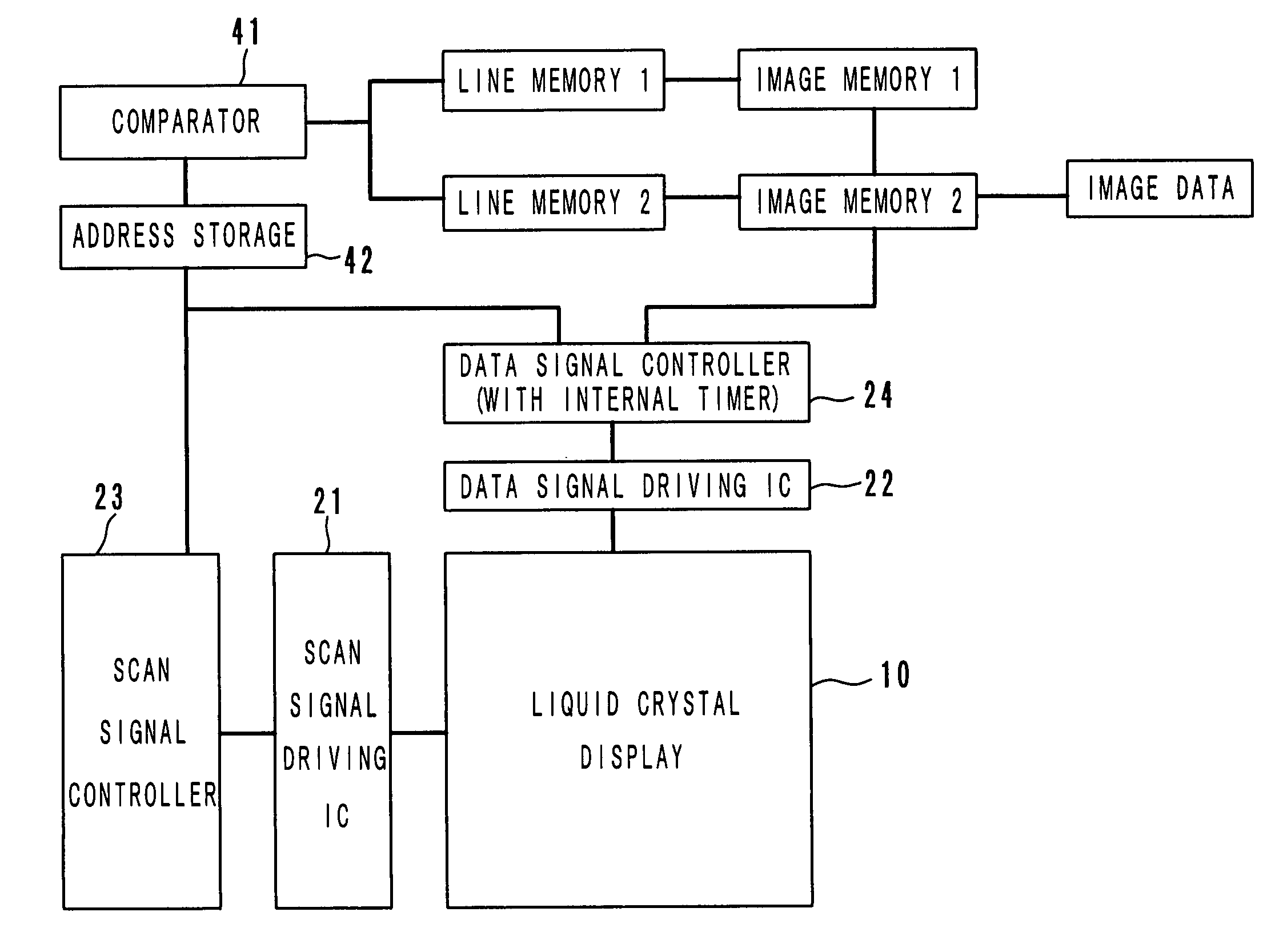
[0010]An object of the present invention is to provide a liquid crystal display device which is small, thin and light to be portable, and does not require glass substrates for safety, makes an even display and consumes little electric power.
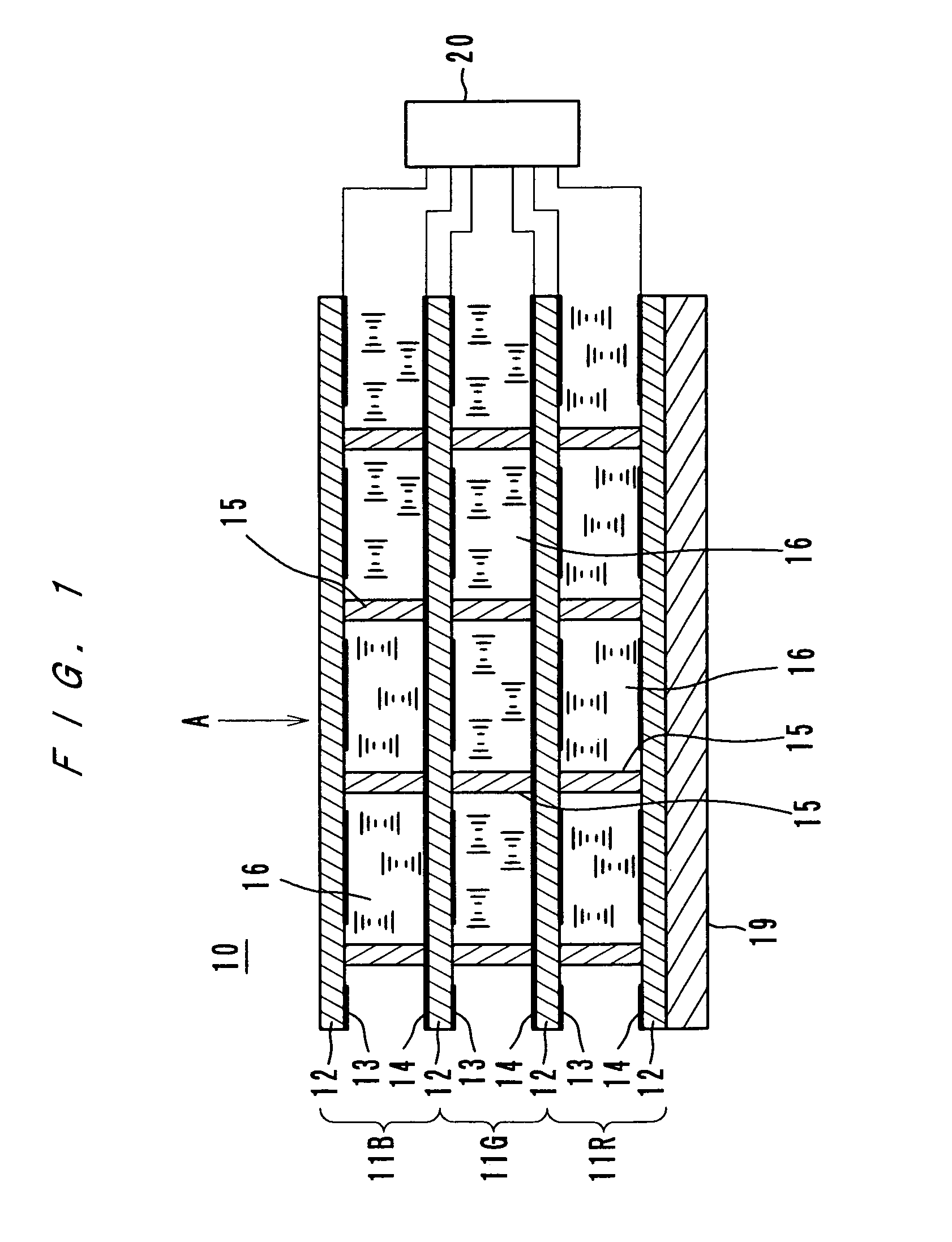
[0015]According to the present invention, a reflective liquid crystal display with a memory effect is used. It is preferred to use liquid crystal which exhibits a cholesteric phase in a room temperature (for example, chiral nematic liquid crystal) as the liquid crystal material. Such a liquid crystal with a memory effect does not require glass substrates, and there is no fear that the display will be fragile. With respect to such a liquid crystal display, the alignment control is easy, the angle of field is large, and a problem of unevenness does not arise even if the display is large. Moreover, because the liquid crystal has a memory effect, the display does not consume electric power to maintain a display, which means that the display is economic and is not influenced by noise, and the display can maintain a display even if electric power is cut off.
[0018]The phase transition drive is a known method, and by adopting this method, the time required for reset to a homeotropic state is shorter. In the phase transition drive method, only a display of a two-value image by on and off of a pulse voltage is possible. However, because this shortens the time to make a display, this method is used as a method for operation in a rapid mode to display a large volume of information (a plurality of images) for a short time as in a mode of turning the pages for skimming. As will be described in the following embodiments, a display in a mode of turning the pages is possible in various drive methods, and the use of the liquid crystal display as an electronic book becomes more convenient.
[0020]Further, by displaying new information so as not to overlap the information currently displayed, the time for erasing overlap portions and displaying new information thereon can be saved, and the time for switching images can be shortened. If a film type speaker is installed, a display device with an audio function can be obtained, and in the rapid mode, audio information compensates for lack of visual information.

Problems solved by technology

At present, information is widely distributed by use of printed matter; it, however, increases the volume of garbage and promotes exhaustion of forest resource for paper pulp.
A reflective liquid crystal display with a memory effect, however, has a drawback that the response speed to a driving voltage is low.
In a type which uses glass substrates, when large substrates are used, it is difficult to take a rubbing alignment treatment on the substrates evenly, and consequently, the substrates are fragile.
Also, the angle of field of the display area is narrow, and it is difficult to read information displayed thereon.
Moreover, if a shock or pressure is applied to the display substrates, the alignment comes out of order, and reading of information becomes impossible.
Further, the liquid crystal itself is volatile, and for a display of information, electric power must be supplied to the display device constantly and continuously, that is, the power consumption of the liquid crystal display is large.

Method used


Image

  • Liquid crystal display device and driving method thereof
  • Liquid crystal display device and driving method thereof
  • Liquid crystal display device and driving method thereof

Examples


Embodiment Construction

[0053]Embodiments of liquid crystal display devices and driving method thereof according to the present invention are described with reference to the accompanying drawings.

Display Device Using Liquid Crystal Which Exhibits a Cholesteric Phase

[0054]A liquid crystal display which has cholesteric liquid crystal or chiral nematic liquid crystal between two substrates makes a display by switching the liquid crystal between a planar state and a focal-conic state. In the planar state, the liquid crystal selectively reflects light of a wavelength λ=P n (P: helical pitch of the cholesteric liquid crystal, n: average refractive index of the liquid crystal). In the focal-conic state, if the wavelength of light selectively reflected by the cholesteric liquid crystal is in the infrared spectrum, the liquid crystal scatters light, and if the wavelength of light selectively reflected is shorter than the infrared spectrum, the liquid crystal transmits visible light. Therefore, by setting the wavele...


PUM


Abstract

A display device which has a liquid crystal display having a liquid crystal material, a driver for driving the liquid crystal display, and a controller for controlling the driver to drive at least a part of the liquid crystal display by selectively using one of a first drive method and a second drive method which are different from each other in operational principle of the liquid crystal material. The pulse voltage to drive at least one pixel of the liquid crystal display can be selectively set to any one of a plurality of kinds. The data pulse voltage applied to a data electrode can be selectively set to any one of a plurality of kinds to drive at least one pixel of the liquid crystal.

Description

[0001]This application is based on application Nos. 10-326387 and 10-341918 filed in Japan, the content of which is hereby incorporated by reference.BACKGROUND OF THE INVENTION[0002]1. Field of the Invention[0003]The present invention relates to a liquid crystal display device and a driving method thereof, and more particularly to a reflective liquid crystal display device with a memory effect and a driving method thereof.[0004]2. Description of Prior Art[0005]At present, information is widely distributed by use of printed matter; it, however, increases the volume of garbage and promotes exhaustion of forest resource for paper pulp. The present inventors think that these problems can be eased by developing a system of providing information being stored in digital information recording media so that users can get the information by use of display devices such as liquid crystal displays. Accordingly, they have developed an electronic book system using liquid crystal display devices. T...

Claims


Application Information

Patent Timeline
IPC IPC(8): G09G3/36
CPCG09G3/36G09G3/3622G09G3/3648
Inventor MASAZUMI, NAOKIYAMAKAWA, EIJIHOTOMI, HIDEO
Owner MINOLTA CO LTD
Learn More