
Presses with vision inspection

A visual inspection and stamping machine technology, applied in metal processing, metal processing equipment, manufacturing tools, etc., can solve the problems of difficult positioning of printed patterns, increased coil waste rate, and feeding errors, so as to achieve no cumulative error and reduce Small coil waste rate, effect of eliminating errors

Active Publication Date: 2016-02-10
易视智瞳科技(深圳)有限公司
View PDF6 Cites 0 Cited by
  • Summary
  • Abstract
  • Description
  • Claims
  • Application Information

AI Technical Summary

Problems solved by technology

[0004] However, the coil material may be deformed after the stamping process. When stamping over the feed material, there may be a feed error, which makes it difficult for the printed pattern to be located at the set position of the punched part. Although currently in the stamping process, the above errors are in the It is within the acceptable range, but when the coil material is processed, after multiple stamping processes, the above errors will gradually accumulate, and after a certain number of stampings, the position difference between the position of the printed pattern and the set position of the punched part exceeds the error range, not only It will increase the waste rate of coil materials, which will bring problems to the stamping of the subsequent process: the deviation of the stamping pattern will also produce a large number of waste products, and the defects are obvious

Method used


Image

  • Presses with vision inspection
  • Presses with vision inspection

Examples


Embodiment Construction

[0022] In order to facilitate the understanding of those skilled in the art, the present invention will be further described below in conjunction with the embodiments and accompanying drawings, and the contents mentioned in the embodiments are not intended to limit the present invention.

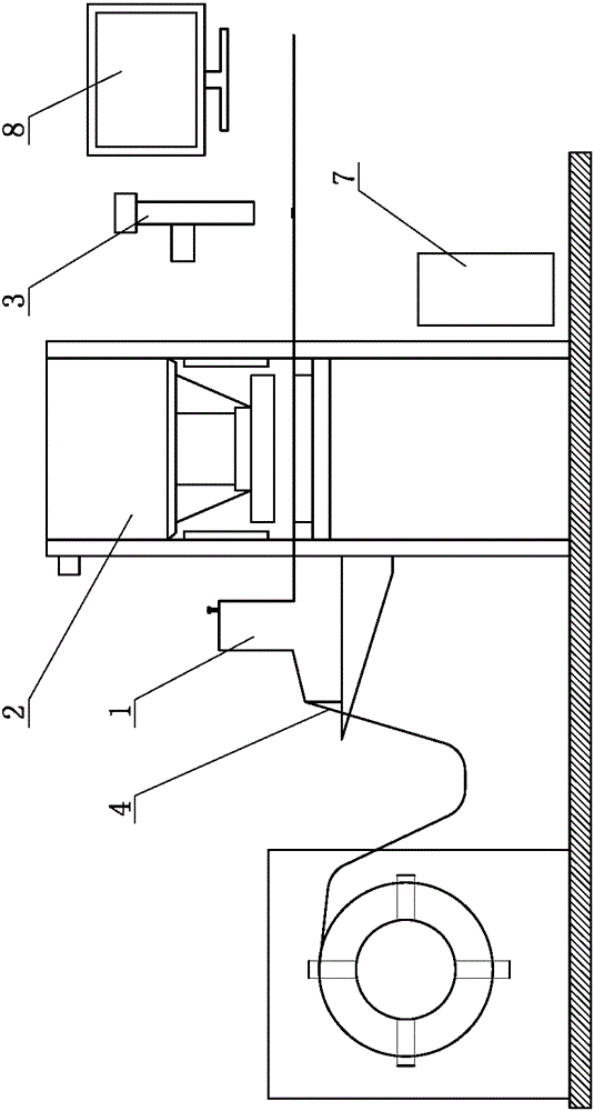
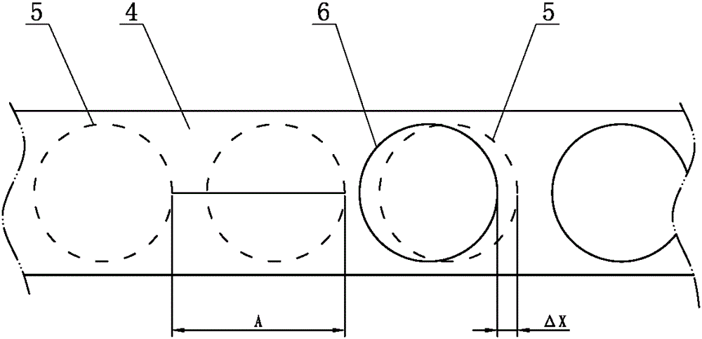
[0023] Such as figure 1 and figure 2 Shown is a first embodiment of a punching machine with visual detection in the present invention, including a feeding mechanism 1, a punching device 2 and an image acquisition device 3, and also includes a feeding controller electrically connected to the feeding mechanism 1, the The image acquisition device 3 is electrically connected to the feed controller, the image acquisition device 3 is located above the coil material 4 on the discharge side of the stamping device 2, and the coil material 4 is provided with a mark reference 5;

[0024] The image acquisition device 3 captures the image of the punched coil material 4 and transmits it to the feed cont...


PUM


Abstract

The invention relates to the technical field of punching equipment, in particular to a punch with a visual inspection function. The punch comprises a feeding mechanism, a punching device, an image collecting device and a feeding controller electrically connected with the feeding mechanism. The image collecting device is electrically connected with the feeding controller and is located above a coil stock on a discharge side of the punching device, and the coil stock is provided with a mark datum; the image collecting device shoots an image of the punched coil stock and transmits the image to the feeding controller, and the feeding controller extracts the mark datum and an X position of an actual punching position and calculates the position difference delta X between the mark datum and the actual punching position; the feeding mechanism adjusts feeding displacement L of each feeding process according to the position difference delta X. According to the punch, various errors generated in the punching process are eliminated accurately, machining accuracy of coil stock punching is greatly and effectively improved, the waste rate of the coil block is reduced, accumulative errors are avoided, deviation of punched patterns can also be reduced greatly, and the practicability is high.

Description

technical field [0001] The invention relates to the technical field of stamping processing equipment, in particular to a stamping machine with visual detection. Background technique [0002] In the field of traditional printed iron products, the technological process is: coating - printing - drying - stamping - forming. [0003] The substrate used for printed iron products is tinplate or other metal sheets. To be coated before printing. Usually, the front side of the printing substrate needs to be coated and printed, and the inner side needs to be coated with paint to ensure that the printed iron product has a good appearance decoration requirement. Printing is to print patterns on tinplate or other metal sheets through an offset printing machine, and then punch holes in the corresponding positions of the printed patterns so that the printed patterns are just at the set position of the punched parts. [0004] However, the coil material may be deformed after the stamping p...

Claims


Application Information

Patent Timeline
Patent Type & Authority Patents(China)
IPC IPC(8): B21D28/24B21C51/00
Inventor 苏思妮
Owner 易视智瞳科技(深圳)有限公司
Learn More