
Automatic feeder used for arc welding

An automatic feed and arc technology, applied in welding equipment, auxiliary welding equipment, welding/cutting auxiliary equipment, etc., can solve the problems of low concentricity accuracy, low preparation, and inability to rotate workpieces to be welded

Inactive Publication Date: 2014-04-09
WENZHOU POLYTECHNIC
View PDF7 Cites 16 Cited by
  • Summary
  • Abstract
  • Description
  • Claims
  • Application Information

AI Technical Summary

Problems solved by technology

[0003] The existing welding positioner only fixes the workpiece to be welded, and cannot adjust the angle of the workpiece to be welded, nor can it rotate the workpiece to be welded. In order to achieve the best welding position during the welding process, it is necessary to adjust the welding position. The position of the equipment, in other words, in the existing welding process, the workpiece to be welded is fixed, and the welding equipment moves. During the welding process, the welding equipment needs to select the best welding position, and the welding equipment is selected during the selection process. On the one hand, the degree of preparation is not high, on the other hand, it is troublesome and time-consuming, which leads to low work efficiency and increases the labor intensity of workers
[0004] In addition, the existing welding positioner is more troublesome to install workpieces to be welded with different diameters, and the concentricity accuracy is not high

Method used


Image

  • Automatic feeder used for arc welding
  • Automatic feeder used for arc welding
  • Automatic feeder used for arc welding

Examples


Embodiment Construction

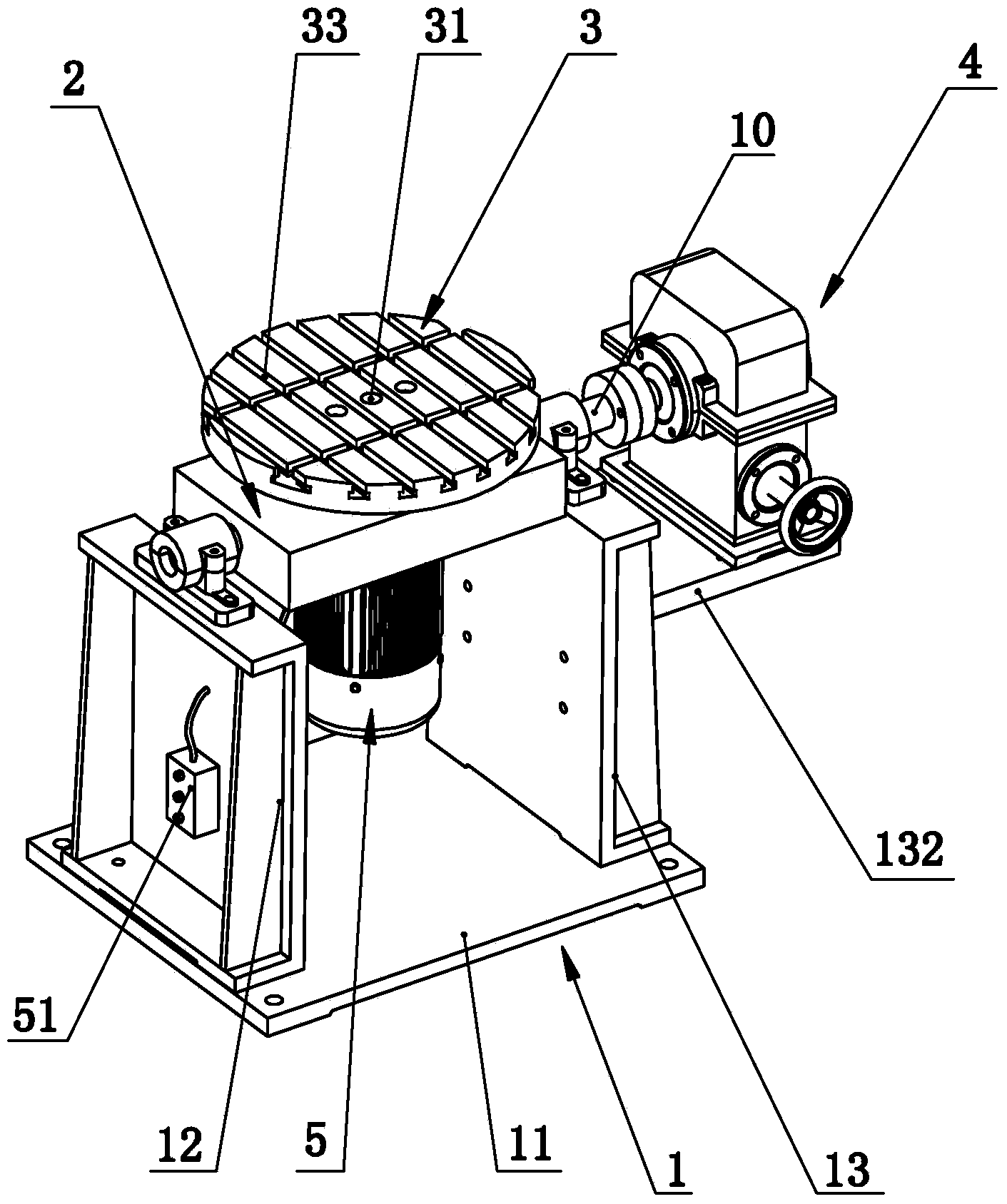
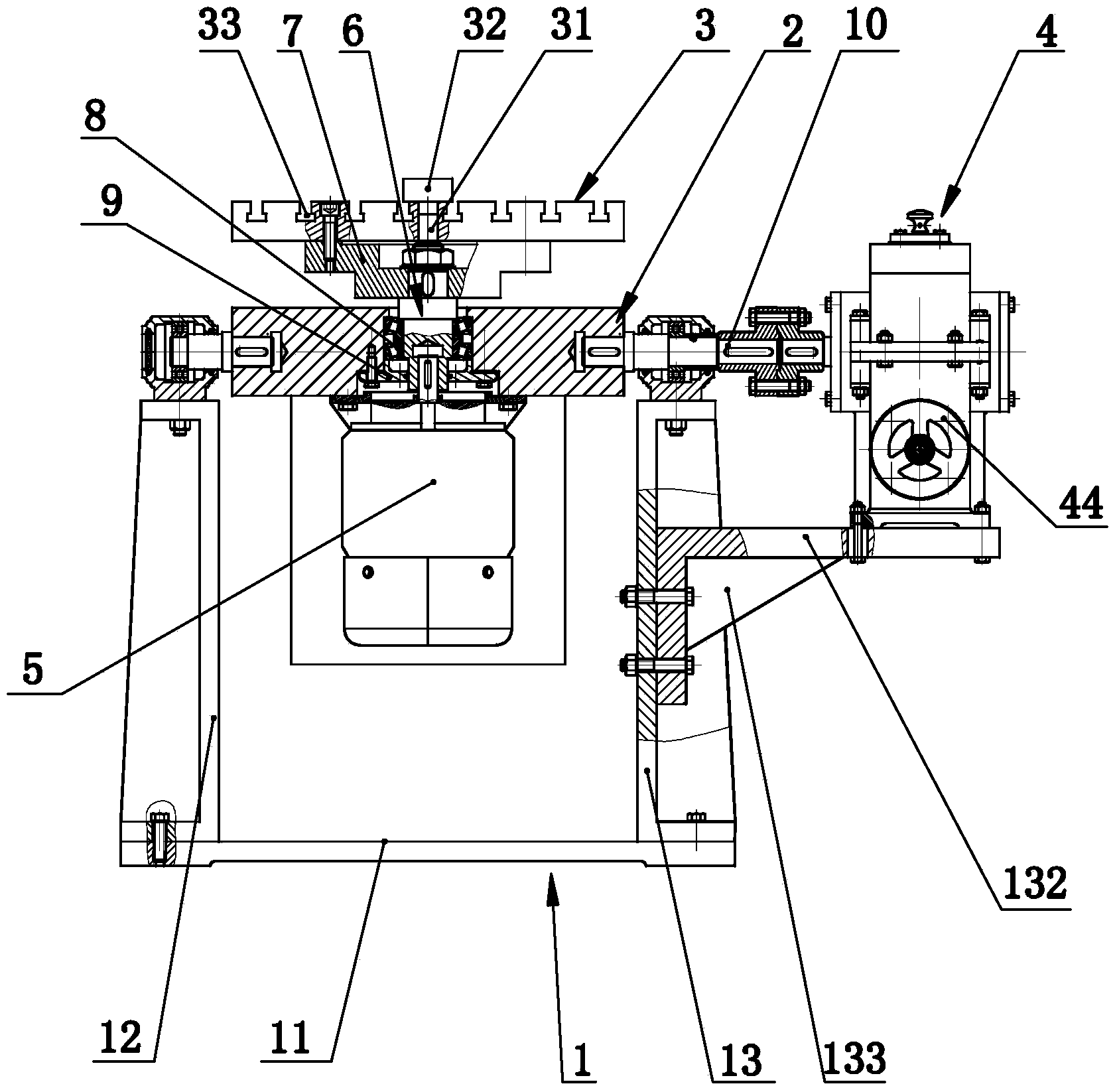
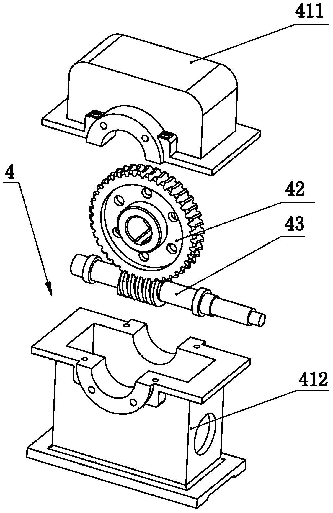
[0025] Such as Figure 1-5 As shown, an automatic feeder for arc welding includes a fixed frame 1 and an overturn table 2, the overturn table 2 is arranged on the fixed frame, and the overturn table 2 is provided with a bracket panel 3 for fixing workpieces, and the overturn table 2 is provided with a turning mechanism 4 for adjusting the turning angle of the turning platform 2, and a motor 5 for driving the rotation of the bracket panel 3 is arranged below the turning platform 2. The output shaft of the turning mechanism 4 is perpendicular to the output shaft of the motor 5. The present invention It also includes a switch 51 to control the operation of the motor. The motor 5 of the present invention is preferably a variable frequency motor. By adopting the above-mentioned technical scheme, the turning mechanism 4 can make the turning table 2 turn over in both directions, that is, adjust the workpiece on the bracket panel 3, so that the workpiece is in the most optimal position...


PUM


Abstract

The invention relates to an automatic feeder used for arc welding. The automatic feeder used for arc welding comprises a fixing frame and an overturning table, wherein the overturning table is arranged on the fixing frame. The automatic feeder used for arc welding is characterized in that a bracket panel used for fixing a workpiece is arranged on the overturning table, an overturning mechanism used for adjusting the overturning angle of the overturning table is arranged above the overturning table, a motor used for driving the bracket panel to rotate is arranged below the overturning table, and an output shaft of the overturning mechanism is perpendicular to an output shaft of the motor. The automatic feeder used for arc welding has two degrees of freedom which enable the workpiece to be overturned in two directions as well as rotated continuously in the forward direction and in the reverse direction, the workpiece can be located on an optimum welding position, and automatic and continuous feeding of workpieces is achieved. An axial positioning hole used for workpiece installation is formed in the center of the bracket panel, and as a result, installation accuracy, operation accuracy, welding quality of welding seams and production efficiency are improved greatly, labor intensity of workers is relieved, and the efficacy of various welding methods can be brought into full play.

Description

technical field [0001] The invention relates to a welding positioner, in particular to an automatic feeder for arc welding. Background technique [0002] In the field of welding, the welding positioner is classified as a welding auxiliary machine, and the welding positioner is matched with other welding equipment to form a semi-automatic or fully automatic welding machine. [0003] The existing welding positioner only fixes the workpiece to be welded, and cannot adjust the angle of the workpiece to be welded, nor can it rotate the workpiece to be welded. In order to achieve the best welding position during the welding process, it is necessary to adjust the welding position. The position of the equipment, in other words, in the existing welding process, the workpiece to be welded is fixed, and the welding equipment moves. During the welding process, the welding equipment needs to select the best welding position, and the welding equipment is selected during the selection proc...

Claims


Application Information

Patent Timeline
IPC IPC(8): B23K37/047B23K37/00
CPCB23K37/047
Inventor 陈崇炯黄爱书许海军余晓军潘建乐胡子贤王强
Owner WENZHOU POLYTECHNIC
Learn More