Rapid installation device and method for hydraulic breaking hammer drill rod base assembly drill rod bushing

A technology of hydraulic breaker and installation device, applied in metal processing, metal processing equipment, manufacturing tools, etc., can solve problems such as shortening the service life of products, scratching of bushings and drill rod seats, and wear of drill rods and bushings, etc. Achieve the effect of improving assembly efficiency, reducing quality accidents and ensuring assembly quality

Inactive Publication Date: 2014-04-09
MAANSHAN BOWEI MACHINERY MFG
View PDF13 Cites 1 Cited by
  • Summary
  • Abstract
  • Description
  • Claims
  • Application Information

AI Technical Summary

Problems solved by technology

[0003] There are the following problems in the large gap: 1. The bushing is manually knocked into the drill rod seat during installation, which may easily cause scratches between the bushing and the drill rod seat; 2. When the reversing valve of the hydraulic breaker is switched When working in the opposite direction, the hydraulic energy of 2-5 kilojoules is converted into mechanical energy and transmitted to the drill rod to do work on the outside, and the outside world also produces a strong and approximately equal reaction force on the drill rod. On the one hand, it will cause a large amount of energy loss, on the other hand, the drill rod and the bushing will be severely worn, which shortens the service life of the product; moreover, when the drill rod is impacted by complex alternating forces, due to the existence of a large gap, the The drill rod shakes in the bushing, causing the drill rod to bend, causing the piston rod, the core component of the main engine, to strain the cylinder, resulting in serious quality accidents

Method used


Image

  • Rapid installation device and method for hydraulic breaking hammer drill rod base assembly drill rod bushing
  • Rapid installation device and method for hydraulic breaking hammer drill rod base assembly drill rod bushing
  • Rapid installation device and method for hydraulic breaking hammer drill rod base assembly drill rod bushing

Examples


Embodiment Construction

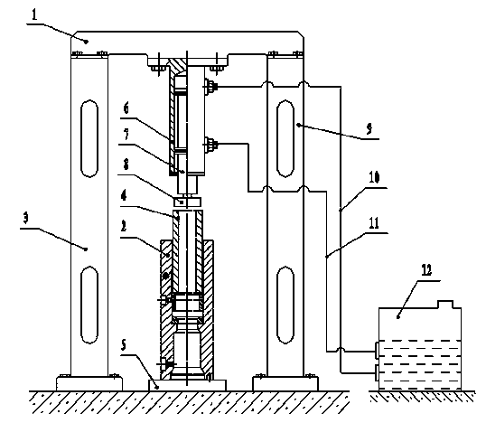
[0017] Such as figure 1 As shown, the rapid installation device for the drill rod bushing of the hydraulic breaker drill rod seat assembly of the present invention includes a beam 1, a left column 3, a pressure sleeve 4, a cylinder seat 6 of a high-pressure oil cylinder, a piston 7, a pressure rod 8, and a right column 9. The high-pressure oil inlet circuit 10, the low-pressure oil return circuit 11, the hydraulic station 12, the left and right columns 3, 9 and the hydraulic station 12 are fixed on the base surface, and the left and right columns 3, 9 and the beam 1 are connected by fasteners to form a The whole frame, the cylinder seat 6 of the high-pressure oil cylinder is fixedly arranged directly under the beam 1, and the head of the piston 7 inside is connected with the pressure rod 8, and the cylinder seat 6 of the high-pressure oil cylinder passes through the high-pressure oil inlet circuit 10 and the low-pressure oil return circuit 11 It communicates with the hydraulic...


PUM


Abstract

The invention discloses a rapid installation device for a hydraulic breaking hammer drill rod base assembly drill rod bushing. The rapid installation device comprises a beam, a left stand column, a pressing sleeve, a high-pressure oil cylinder base, a piston, a pressing rod, a right stand column, a high-pressure oil inlet loop, a low-pressure oil return loop and a hydraulic station. The left stand column, the right stand column and the hydraulic station are fixedly arranged on a base face. The left stand column, the right stand column and the beam are connected through fasteners to form a whole rack body. The high-pressure oil cylinder base is fixedly arranged under the beam. The head of the piston inside a high-pressure oil cylinder is connected with the pressing rod. The high-pressure oil cylinder base is communicated with the hydraulic station through the high-pressure oil inlet loop and the low-pressure oil return loop. The invention further discloses an installation method for the hydraulic breaking hammer drill rod base assembly drill rod bushing. According to the rapid installation device and method for the hydraulic breaking hammer drill rod base assembly drill rod bushing, the drill rod bushing and a drill rod base can be rapidly installed, assembling efficiency is improved, and assembling quality is ensured.

Description

technical field [0001] The invention relates to the installation of key components of a hydraulic breaker, in particular to a quick installation device and an installation method for a drill rod bushing of a drill rod seat assembly of a hydraulic breaker. Background technique [0002] The drill rod seat assembly in the hydraulic breaker currently on the market mainly includes the drill rod seat, the drill rod, the drill rod front bushing, the drill rod rear bushing, the limit bushing; the drill rod front bushing, the drill rod The outer circle of the bushing behind the rod, the limit bushing and the inner hole of the drill rod seat are fitted through clearance fit. The conventional design fit clearance is: +0.012~+0.069 below φ140, +0.014~+0.081 above φ160, Due to the processing accuracy, the actual gap produced is controlled at about +0.05. [0003] There are the following problems in the large gap: 1. The bushing is manually knocked into the drill rod seat during inst...

Claims


Application Information

Patent Timeline
Patent Type & Authority Applications(China)
IPC IPC(8): B23P19/027
CPCB23P19/027
Inventor 刘云鸽汪丽芳
Owner MAANSHAN BOWEI MACHINERY MFG
Why Eureka
Try Eureka