3D printing method for building beam component

A technology of 3D printing and beam components, applied in the field of 3D printing technology, can solve the problem of less application of 3D printing technology, achieve the effect of high quality, reduce labor costs and production costs, and improve manufacturing efficiency

Active Publication Date: 2014-04-09
无锡华工大光电智能科技有限公司
View PDF4 Cites 31 Cited by
  • Summary
  • Abstract
  • Description
  • Claims
  • Application Information

AI Technical Summary

Problems solved by technology

However, the application of 3D printing technology in the man

Method used


Image

  • 3D printing method for building beam component
  • 3D printing method for building beam component

Examples


Example Embodiment

[0019] The present invention will be further described in detail below with reference to the accompanying drawings, so that those skilled in the art can implement it with reference to the description.
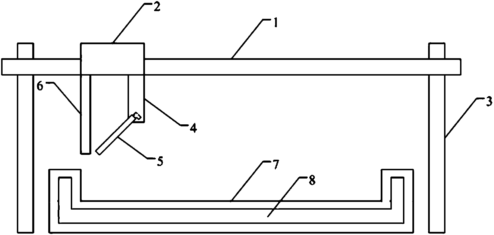
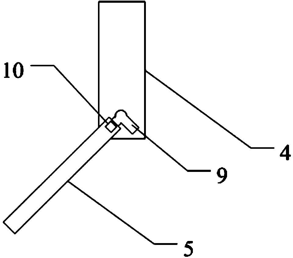
[0020] like figure 1 As shown, the present invention provides a 3D printing method for building beam components, including the following steps: step 1, manufacturing a forming mold frame, the forming mold frame has a square groove 7 opened on one side, and the forming mold frame also A cavity 8 is provided, and the cavity 8 wraps the square groove in the middle; Step 2: Manufacture a support frame 3, and a beam 1 can move in a vertical direction relative to the support frame 3 On the beam, a traveling mechanism 2 is arranged on the beam in a movable manner along the beam, a printing mechanism and a hot steam jetting mechanism 6 are mounted on the traveling mechanism, and the hot steam jets The mechanism is arranged on the back side of the printing mechanism, a computer is conn...


PUM


Abstract

The invention discloses a 3D printing method for a building beam component. The method comprises the steps of manufacturing a forming mold frame, wherein the forming mold frame is provided with a square groove with an opening in one side and a cavity, and the square groove is wrapped by the cavity; manufacturing a supporting frame body, wherein a printing mechanism and a heat steam jetting mechanism are mounted on a walking mechanism; adding heat exchange media to the cavity in advance, wherein the inner surface temperature of the forming mold frame reaches 35-40 DEG C; generating a 3D CAD model of the beam component on a computer, wherein the thickness of a concrete layer corresponding to each cross section layer is 5-10cm; sending a control command to the walking mechanism by the computer, and enabling the walking mechanism to do reciprocating movement on a beam, wherein the hot steam jetting mechanism jets hot steam to the surface of the formed concrete layer, and the temperature of the hot steam is 40-45 DEG C. According to the method, the manufacturing efficiency of the building beam component can be improved, labor cost and production cost are lowered, and due to the more precise control over the production process, the product with the higher quality can be obtained.

Description

technical field [0001] The invention relates to a 3D printing technology, in particular to a 3D printing method for building beam components. Background technique [0002] The traditional 3D printing technology is based on the computer 3D design model, through the software layered discrete and numerical control forming system, using laser beams, hot-melt nozzles, etc., to accumulate special materials such as metal powder, ceramic powder, plastic, cell tissue Knots, and finally superimposed molding to create a physical product. This digital manufacturing mode does not require complex processes or a lot of manpower, and can generate parts of any shape directly from computer graphics data, with high precision and quality. However, the application of 3D printing technology in the manufacture of engineering structures is still relatively small. Contents of the invention [0003] The object of the present invention is to provide a 3D printing method for building beam component...

Claims


Application Information

Patent Timeline
IPC IPC(8): B28B1/00
CPCB28B1/001
Inventor 吕诗林
Owner 无锡华工大光电智能科技有限公司
Why Eureka
Try Eureka